Multilayered printed circuit board, more particularly flame-resistant and/or smoke-suppressing multilayered printed circuit board

a printed circuit board and multi-layer technology, applied in the direction of printed circuit manufacturing, printed circuit aspects, electrical equipment, etc., to achieve the effects of reducing costs, improving or increasing flame resistance, and high conductivity

Active Publication Date: 2015-10-13
AT & S AUSTRIA TECH & SYSTTECHN AG
View PDF10 Cites 1 Cited by
  • Summary
  • Abstract
  • Description
  • Claims
  • Application Information

AI Technical Summary

Benefits of technology

[0009]To solve these objects, a multilayered printed circuit board of the initially defined kind is essentially characterized in that a solder mask is each additionally provided on outwardly facing layers being composed of the incombustible, conductive material. Due to the fact that the printed circuit board contains in its interior at least two layers each having a high surface portion of at least 50%, more particularly at least 70%, composed of the incombustible, conductive material, it will be ensured that in the event of both an exposure to elevated temperatures and, as the case may be, the direct exposure to a flame or fire, only partial regions of such a printed circuit board will possibly be destroyed or damaged, particularly under the development of smoke due to the non-conductive, resin-like materials usually contained in such a multilayer printed circuit board, while the complete destruction of the printed circuit board over the required test period of, for instance, 4 minutes will, in particular, be largely prevented also reducing or minimizing smoke development. The high surface portion of layers composed of incombustible, conductive and hence, in particular, metallic materials, which are disposed in the interior of the printed circuit board, ensures that the requirements in respect to an accordingly slight smoke development will be reliably met. To further improve the flame resistance, particularly of the outwardly facing surfaces it is proposed for the printed circuit board according to the invention that a solder mask is each additionally provided on the outwardly facing layers composed of the incombustible, conductive material.
[0016]In addition to the arrangement proposed by the invention, of layers or plies of incombustible, conductive material with an accordingly large surface portion in order to improve or increase the flame resistance and / or reduce or suppress the smoke development, the invention also aims to accordingly improve the flammability or combustibility and smoke-developing property of non-conductive materials, particularly dielectrics, usually employed in the production of a multilayer printed circuit board. In this context, it is proposed according to a further preferred embodiment that flame-retardant and / or smoke-suppressing fillers such as, e.g., Al(OH)3SiO2 and the like are added to the layer(s) composed of the non-conductive material, and / or a layer composed of a non-conductive material is covered by a flame-resistant layer, e.g. a polyimide layer. By using such fillers or additives, and / or covering with flame-retardant materials, the flame-resistance of the multilayer printed circuit board according to the invention will be further improved, thus enabling the requirements of, for instance, the initially mentioned smoke density tests to be met in an accordingly simpler and more reliable manner. A successful test can thus also be achieved with multilayer printed circuit boards which, due to the increasing complexity of the structures of such multilayer printed circuit boards, are provided or formed with accordingly higher portions of layers or plies and, in particular, layers composed of non-conductive materials to be inserted between successive layers of conductive material.

Problems solved by technology

Hitherto known constructions and structures of multilayer printed circuit boards have involved the problem of containing comparatively high portions of usually highly combustible, non-conductive materials generally constituting such multilayer printed circuit boards.

Method used


Image

  • Multilayered printed circuit board, more particularly flame-resistant and/or smoke-suppressing multilayered printed circuit board
  • Multilayered printed circuit board, more particularly flame-resistant and/or smoke-suppressing multilayered printed circuit board

Examples


Embodiment Construction

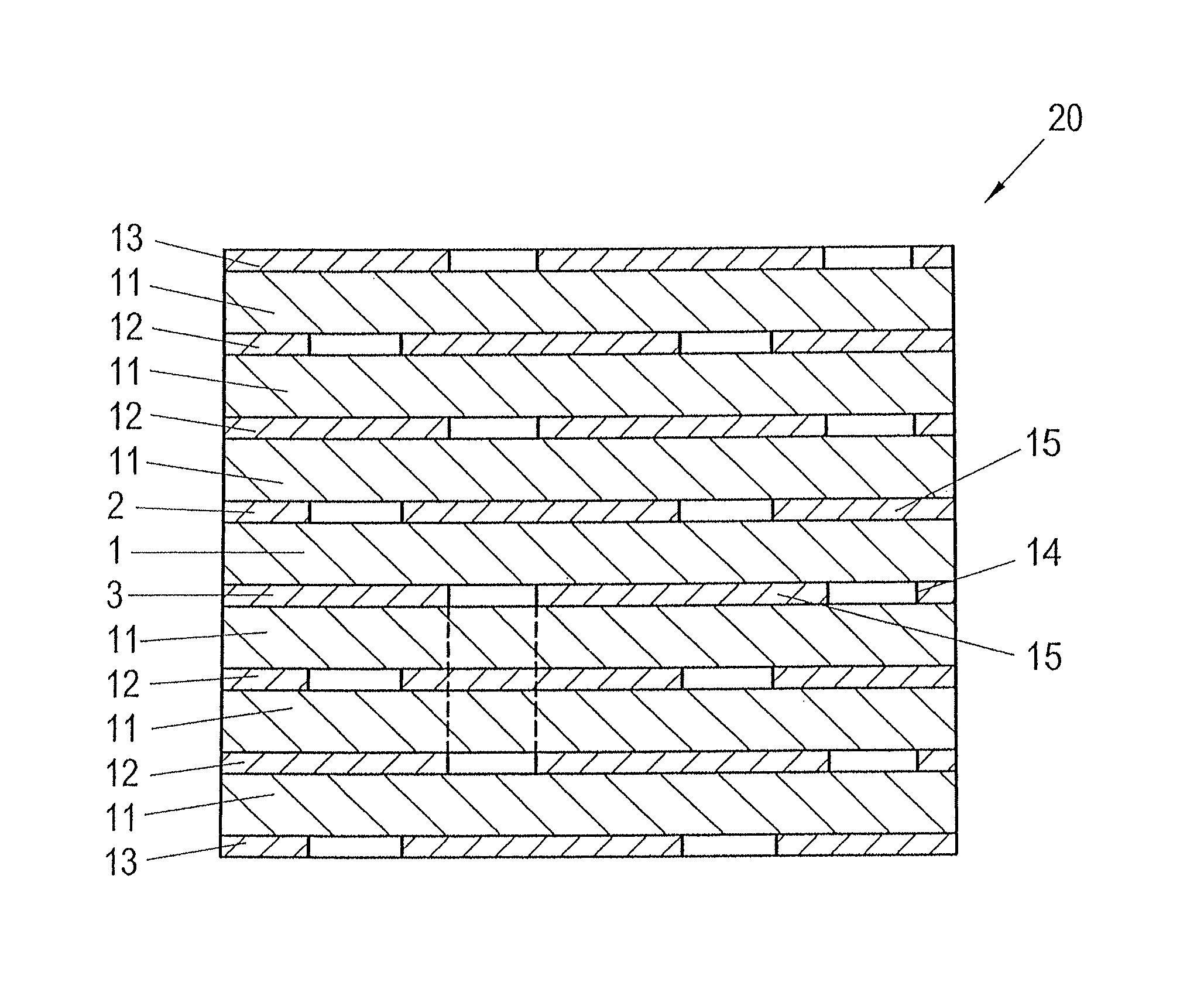
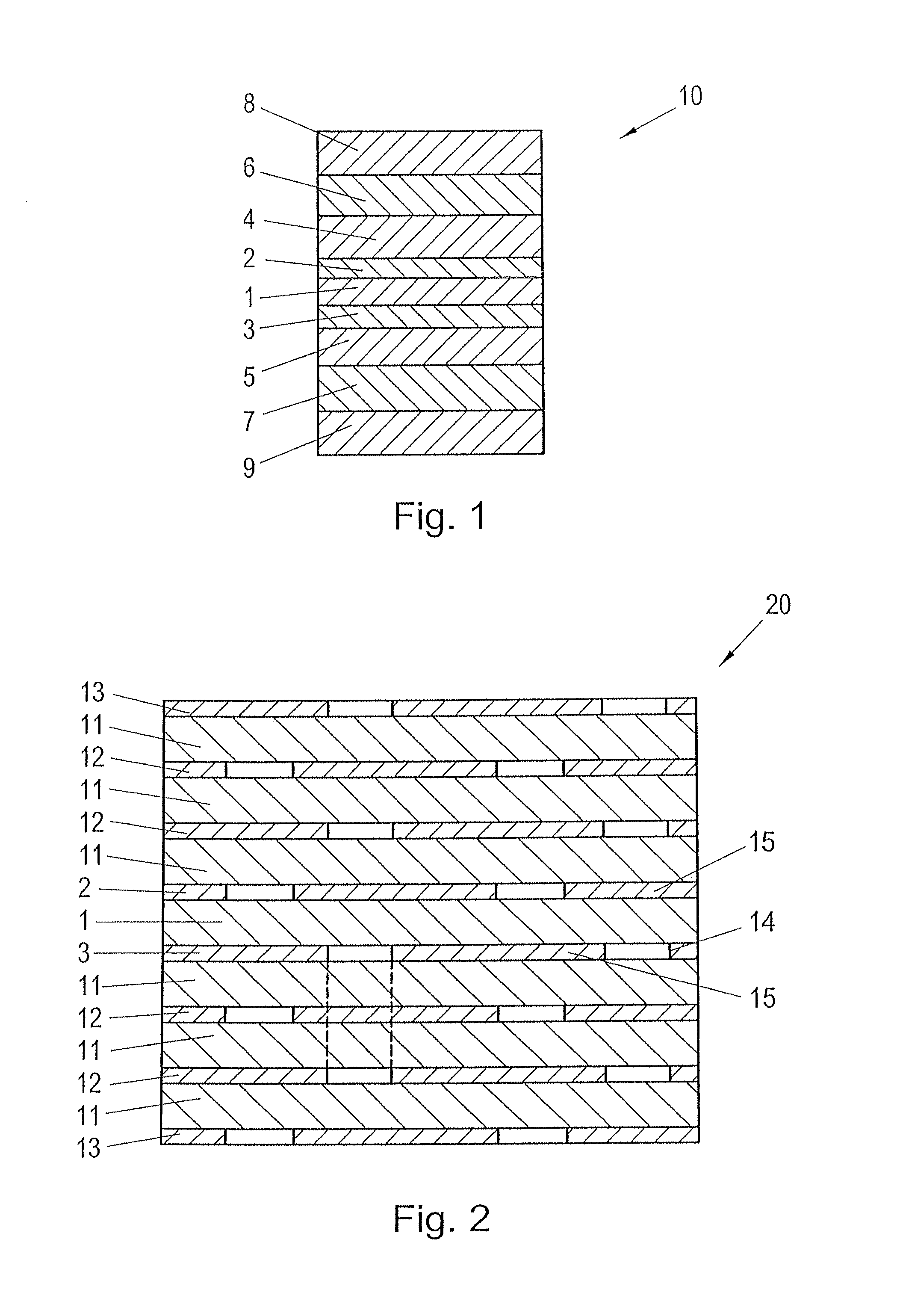
[0023]From the schematic section through a multilayer printed circuit board of a first embodiment according to FIG. 1, it is apparent that, on a core 1, which in the production of multilayer printed circuit boards is, for instance, comprised of a hardened or cured resin material, layers 2, composed of an incombustible, conductive material are disposed, said layers 2, 3 in the illustration according to FIG. 1 being shown as substantially full-surface layers.

[0024]Layers 4, 5 composed of a non-conductive material, in particular dielectric material, are provided consecutively to the layers 2, 3 of incombustible, conductive material.

[0025]On the outwardly facing surfaces of the multilayer printed circuit board generally denoted by 10, layers or plies 6, 7 composed of an incombustible, conductive material are again disposed to adjoin layers 4, 5, wherein no patterning, which is usually provided on such printed circuit boards at last for the externally arranged layers 6, 7 of conductive m...


PUM


Abstract

In the case of a multilayered printed circuit board (20), more particularly a flame-resistant and / or smoke-suppressing multilayered printed circuit board, consisting of a plurality of interconnected layers (2, 3, 12, 13) composed of incombustible, conductive material and layers (1, 11) composed of non-conductive material, two layers (2, 3, 12) composed of a conductive material in each case being separated by at least one layer (1, 11) composed of a non-conductive material, it is provided that the printed circuit board (20) contains in its interior at least two layers (2, 3, 12) having a surface proportion of at least 50%, more particularly at last 70%, composed of the incombustible, conductive material, as a result of which a multilayered printed circuit board (20) having improved flame resistance and reduced smoke evolution can be made available.

Description

[0001]This is national stage of PCT / AT2010 / 000233 filed Jun. 25, 2010 and published in German, which has priority of Austria no. GM 409 / 2009 filed Jun. 30, 2009, hereby incorporated by reference.FIELD OF THE INVENTION[0002]The present invention relates to a multilayered printed circuit board, more particularly a flame-resistant and / or smoke-suppressing multilayered printed circuit board, consisting of a plurality of interconnected layers composed of incombustible, conductive material and layers composed of non-conductive material, two layers composed of conductive material in each case being separated by at least one layer composed of non-conductive material, wherein the printed circuit board contains in its interior at least two layers having a surface proportion of at least 50%, more particularly at least 70%, composed of the incombustible, conductive material.PRIOR ART[0003]A multilayered substrate similar to the kind mentioned above can be taken from US 2003 / 0029830 A1, for inst...

Claims


Application Information

Patent Timeline
Patent Type & Authority Patents(United States)
IPC IPC(8): H05K1/09H05K1/03H05K1/02H05K3/34
CPCH05K1/02H05K1/0298H05K1/0373H05K2201/09309H05K2201/012H05K2201/0209H05K2201/0989H05K3/3452
Inventor FROSCH, RONALDRIEDLER, MANFRED
Owner AT & S AUSTRIA TECH & SYSTTECHN AG
Why Eureka
Try Eureka