Fuel spray nozzle

a fuel spray nozzle and fuel technology, applied in the direction of engines, mechanical equipment, machines/engines, etc., can solve the problems of excessive accumulation of captured particulates in the particulate filter, over-treatment of captured particulates, etc., to prevent deterioration of fuel efficiency and emission of white smoke, and control the fuel flow rate more finely and more accurately

Inactive Publication Date: 2013-03-07
HINO MOTORS LTD
View PDF1 Cites 0 Cited by
  • Summary
  • Abstract
  • Description
  • Claims
  • Application Information

AI Technical Summary

Benefits of technology

[0016]According to the fuel spray nozzle of the invention, various beneficial effects can be exerted as follows.
[0017](I) The turn-down ratio of 10 to 20 times can be realized by employing the duty control, so that a fuel flow rate can be controlled more finely and more accurately. In addition, uniform fine spray can be realized even when a small amount of fuel is injected, so that combustibility and ignitability of the fuel can be substantially improved to prevent deterioration of fuel efficiency and emission of white smoke.
[0018](II) When configuration is made such the at least part of combustion air may be guided as nebulizing air, nebulizing air can be provided by using the part of combustion air without securing a new supply source of nebulizing air, which can substantially reduce a cost for practicing the invention.

Problems solved by technology

However, an amount of captured particulates will exceed an amount of treated particulates in operation areas with low exhaust temperature levels.
Continued operation with such low exhaust temperature levels may hinder sufficient regeneration of the particulate filter, resulting in excessive accumulation of the captured particulates in the particulate filter.

Method used


Image

  • Fuel spray nozzle
  • Fuel spray nozzle
  • Fuel spray nozzle

Examples


Embodiment Construction

[0023]An embodiment of the invention will be described with reference to the drawings.

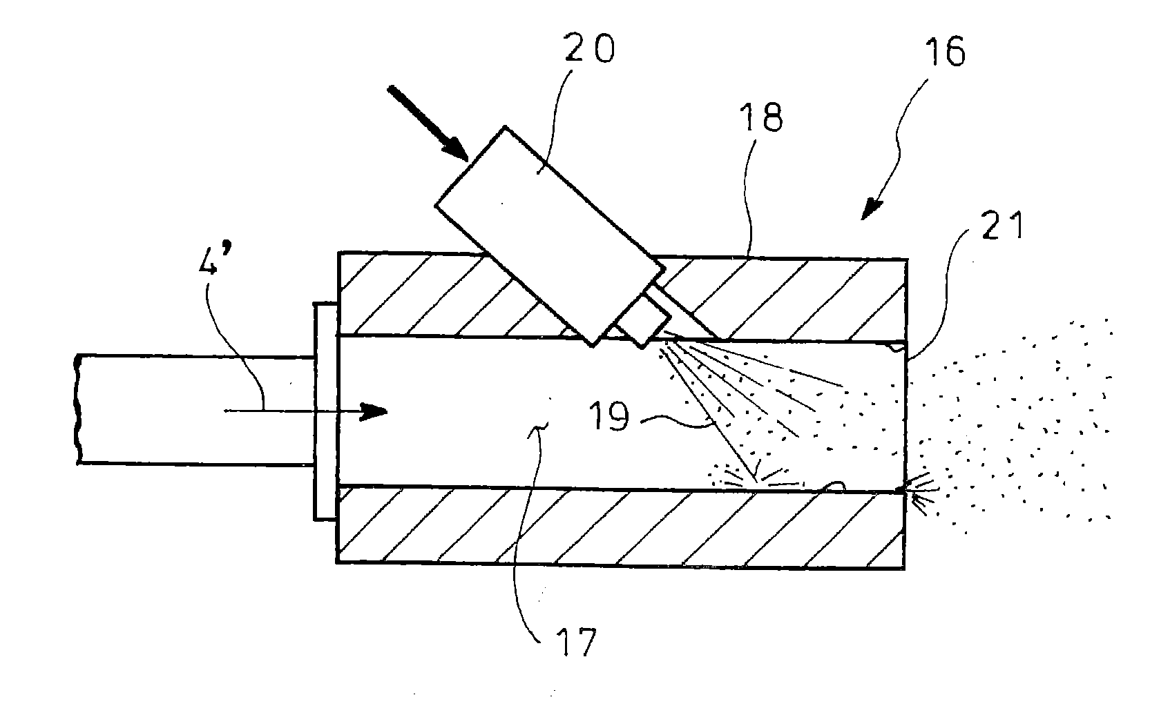
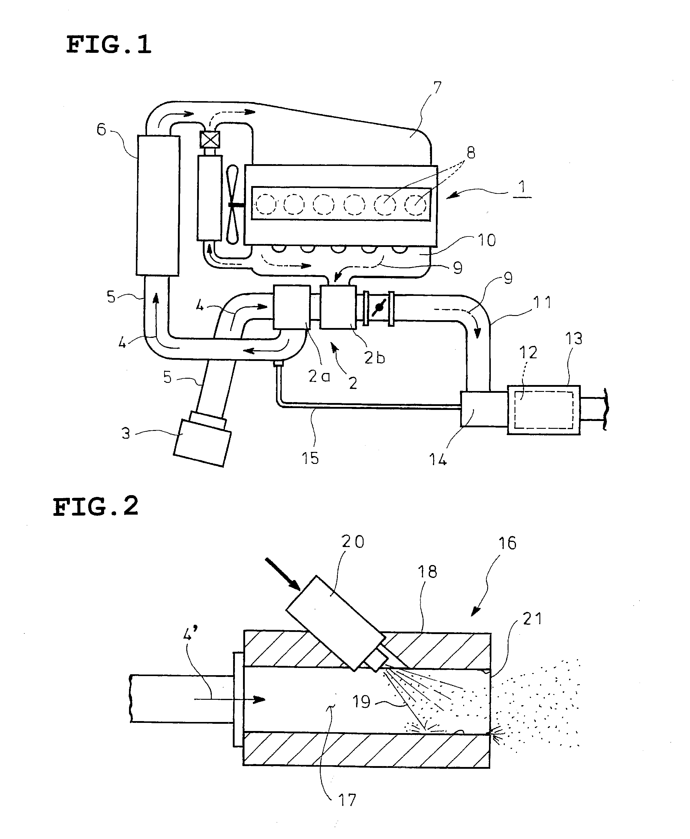
[0024]FIG. 1 shows an embodiment of the invention in which reference numeral 1 denotes a diesel engine equipped with a turbocharger 2. Intake air 4 guided from an air cleaner 3 is sent through an intake pipe 5 to a compressor 2a of the turbocharger 2. The intake air 4 pressurized by the compressor 2a is sent to an intercooler 6 and is cooled. The intake air 4 is further guided from the intercooler 6 to an intake manifold 7 and is distributed to cylinders 8 of the diesel engine 1 (an in-line six-cylinder engine is illustrated in FIG. 1). Exhaust gas 9 discharged from each of the cylinders 8 of the diesel engine 1 is sent through an exhaust gas manifold 10 to a turbine 2b of the turbocharger 2, and after driving the turbine 2b, is sent to an exhaust pipe 11.

[0025]Incorporated in the exhaust pipe 11 is a particulate filter 12 (exhaust purification member) which integrally supports an oxidation catalys...


PUM


Abstract

A fuel spray nozzle 16 has a cylindrical spray block 18 with an inner air passage 17 for flow of nebulizing air 4′ and a fuel injection valve 20 for injection of fuel intermediately of the inner air passage 17 in the spray block 18 at a flow rate adjusted by duty control. The nebulizing air is introduced into the spray block 18 through a base end of the block at a flow velocity of 9 m / s or more and blown out of an injection port 21 at a tip end of the block.

Description

TECHNICAL FIELD[0001]The present invention relates to a fuel spray nozzle.BACKGROUND ART[0002]In a conventional diesel engine, a particular filter is incorporated in an exhaust pipe for flow of an exhaust gas to capture particulates (particulate matters) in the exhaust gas. The particulate filter of this type integrally carries an oxidation catalyst having active species such as Pt or Pd, so that the captured particulates are caused to self-burn even at an minimally low exhaust gas temperature.[0003]However, an amount of captured particulates will exceed an amount of treated particulates in operation areas with low exhaust temperature levels. Continued operation with such low exhaust temperature levels may hinder sufficient regeneration of the particulate filter, resulting in excessive accumulation of the captured particulates in the particulate filter.[0004]Conventionally proposed in this connection is to arrange a combustion appliance for temperature raising of exhaust gas upstrea...

Claims


Application Information

Patent Timeline
Patent Type & Authority Applications(United States)
IPC IPC(8): F02M61/16
CPCF01N3/0256F01N3/30F01N3/36F02B37/00F01N2610/1453Y02T10/144F01N3/0253F01N2610/03F02B37/166Y02T10/12
Inventor TSUMAGARI, ICHIRO
Owner HINO MOTORS LTD
Why Eureka
Try Eureka