Particle capture unit, method for manufacturing the same, and substrate processing apparatus

a technology of substrate processing and capture unit, which is applied in the direction of machine/engine, chemical/physical process, vehicle sealing arrangement, etc., can solve the problems of deteriorating exhaust efficiency, deteriorating exhaust efficiency, and deteriorating exhaust efficiency by decreasing the conductance of the exhaust passage, so as to prevent deterioration of exhaust efficiency and damage of rotational blades

Active Publication Date: 2014-09-02
TOKYO ELECTRON LTD
View PDF19 Cites 0 Cited by
  • Summary
  • Abstract
  • Description
  • Claims
  • Application Information

AI Technical Summary

Benefits of technology

[0008]The present invention provides a particle capture unit which is capable of preventing deterioration of exhaust efficiency and damage of rotational blades and or the like of an exhaust pump, a method for manufacturing the same, and a substrate processing apparatus.

Problems solved by technology

When these floating particles are adhered to a surface of a wafer, a wiring circuit short may occur in a product made from the wafer, such as a semiconductor device, which may result in deterioration of yield of semiconductor devices.
However, the reflecting device disclosed in JP2007-180467A deteriorates exhaust efficiency by decreasing a conductance of an exhaust passage since the reflecting device is arranged to interrupt an exhaust pipe.
As a result, the capture mechanism is protruded into the exhaust pipe, thereby deteriorating the exhaust efficiency by decreasing the conductance of the exhaust passage.
The deterioration of the exhaust efficiency results in increased time taken for vacuum exhaustion of a chamber and low operability of a substrate processing apparatus.
In addition, although JP2007-180467A discloses the capture mechanism formed of a cotton-like material composed of fibers, these fibers are likely to disintegrate from the cotton-like material.
In addition, if some of the disintegrated fibers are dropped on the TMP, rotational blades of the TMP are likely to be damaged.

Method used


Image

  • Particle capture unit, method for manufacturing the same, and substrate processing apparatus
  • Particle capture unit, method for manufacturing the same, and substrate processing apparatus
  • Particle capture unit, method for manufacturing the same, and substrate processing apparatus

Examples


Embodiment Construction

[0025]Hereinafter, embodiments of the present invention will be described with reference to the drawings which form a part hereof.

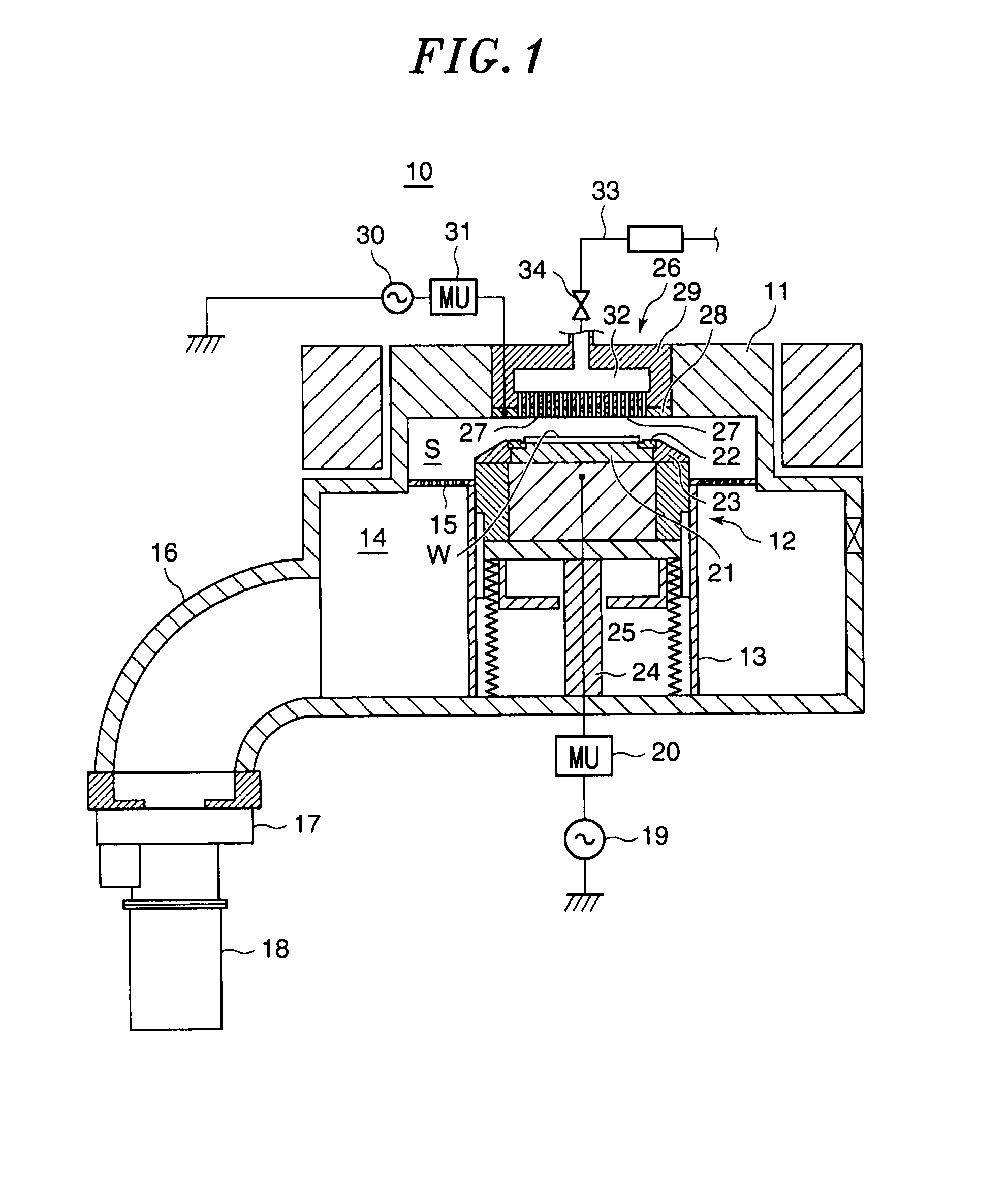
[0026]FIG. 1 is a schematic sectional view showing a configuration of a substrate processing apparatus to which a particle capture unit is applied, in accordance with the embodiment of the present invention.

[0027]As shown in FIG. 1, a substrate processing apparatus 10 that is constructed as an etching processing apparatus for subjecting a semiconductor wafer (hereinafter referring to as a “wafer”) to reactive ion etching (RIE), includes a chamber 11 (processing chamber) which is made of, e.g., aluminum or stainless steel and has a shape with a smaller and a larger cylinders stacked on each other.

[0028]In the chamber 11, a lower electrode 12 as a wafer stage which mounts the wafer and elevates within the chamber 11 with the mounted wafer W and a cylindrical cover 13 covering a side of the elevating lower electrode 12 are disposed.

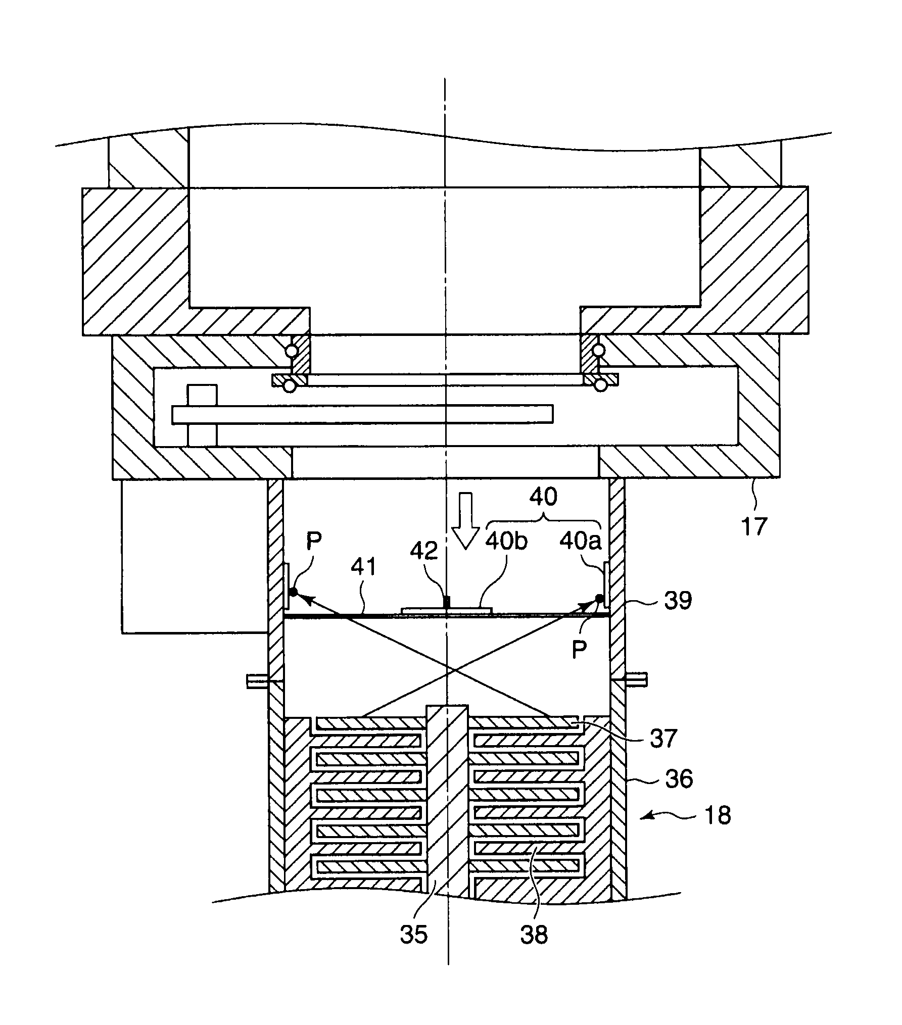
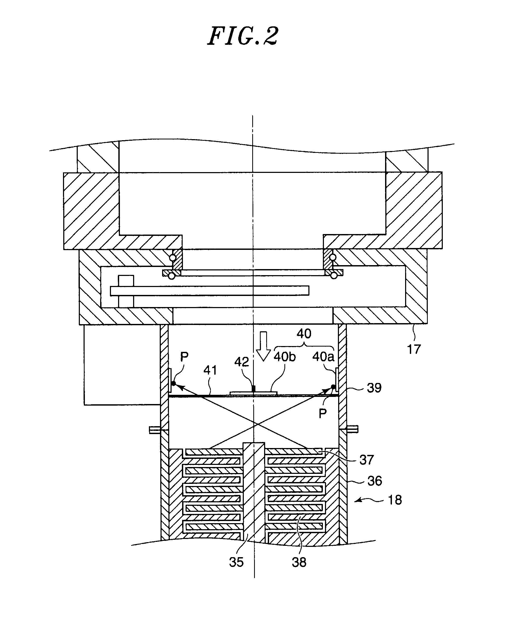
[0029]An annular exhaust p...


PUM

PropertyMeasurementUnit
diameteraaaaaaaaaa
diameteraaaaaaaaaa
diameteraaaaaaaaaa

Abstract

A particle capture unit adopted to be exposed to a space in which particles fly includes at least a first layer formed of a plurality of first fiber-like materials and a second layer formed of a plurality of second fiber-like materials. The first fiber-like materials are thinner than the second fiber-like materials and arrangement density of the first fiber-like materials in the first layer is higher than that of the second fiber-like materials in the second layer, the second layer is interposed between the first layer and the space, and the first and second layers are hardened and bonded together by sintering.

Description

FIELD OF THE INVENTION[0001]The present invention relates to a particle capture unit which is capable of capturing unnecessary particles moving within a substrate processing apparatus, a method for manufacturing the same, and a substrate processing apparatus.BACKGROUND OF THE INVENTION[0002]Typically, a substrate processing apparatus for processing a wafer for a semiconductor device or a substrate such as a glass substrate or the like used to manufacture a FPD (Flat Panel Display) panel such as a LCD (Liquid Crystal Display) panel, a solar cell and the like includes a processing chamber (hereinafter referred to as a “chamber”) in which a substrate to be processed is provided. Deposits on a chamber inner wall or particles resulting from reaction products generated in a specific process are floating in the chamber. When these floating particles are adhered to a surface of a wafer, a wiring circuit short may occur in a product made from the wafer, such as a semiconductor device, which ...

Claims


Application Information

Patent Timeline
Patent Type & Authority Patents(United States)
IPC IPC(8): B01D46/00F04B37/08
CPCF04B37/08Y10S55/05Y10S29/902Y10S264/48Y10T29/49316Y10T156/1043H01L21/02
Inventor MORIYA, TSUYOSHITOYOIZUMI, SYUNSUKETAKAHIRO, KATSUYUKI
Owner TOKYO ELECTRON LTD
Why Eureka
Try Eureka