System and method for electronic adaptive front-lighting

a technology of electronic adaptive frontlighting and system, applied in the direction of lighting and heating apparatus, lighting support devices, instruments, etc., can solve the problems of moving parts presenting many technical challenges, space, weight, and quality constraints, and the standard light distribution b>5/b> cannot be changed,

a technology of electronic adaptive frontlighting and system, applied in the direction of lighting and heating apparatus, lighting support devices, instruments, etc., can solve the problems of moving parts presenting many technical challenges, space, weight, and quality constraints, and the standard light distribution b>5/b> cannot be changed,

US20100213872A1Active Publication Date: 2010-08-26VOLKSWAGEN AG +1

Image

  • System and method for electronic adaptive front-lighting
  • System and method for electronic adaptive front-lighting
  • System and method for electronic adaptive front-lighting

Examples


Embodiment Construction

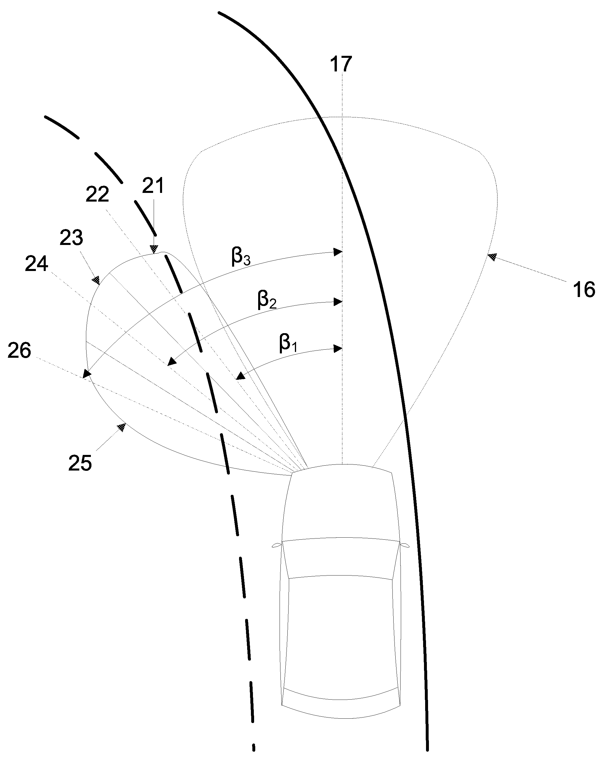
[0063]FIGS. 4 and 5 illustrate example embodiments of a system 11 for electronic adaptive front-lighting (eAFS) of a vehicle. This system 11 may provide a feasible and cost-effective solution to achieve dynamic curve light functionality without moving parts.

[0064]The example embodiments of the system 11, as shown in FIGS. 4 and 5, may include a low-beam light source 12, a high-beam light source 13, a side marker light source 14, and an electronic adaptive front-lighting system light-emitting diode (eAFS LED) module 15. The low-beam, high-beam, and side marker light sources 12, 13, 14 may include any lighting technology, such as incandescent, halogen, xenon, LEDs, etc. The example embodiments shown in FIGS. 4 and 5 include eAFS LED modules 15 having two, three, and four light sectors L1, L2, L3, L4 Each light sector may include one or more LEDs. In addition, FIG. 4 shows the light sectors Lx arranged in a horizontal row, whereas FIG. 5 shows the light sectors Lx arranged in a vertica...


PUM


Abstract

A system and method relates to electronic adaptive front-lighting of a vehicle, including at least one fixed solid state light source. The fixed solid state light source is configured to illuminate a front peripheral region of a vehicle. In addition, the fixed solid state light source is integrated with a daytime running light module of the vehicle.

Description

FIELD OF THE INVENTION[0001]The present invention relates to a system and method for electronic adaptive front-lighting of a vehicle.BACKGROUND INFORMATION[0002]There are some systems available today for adaptive front-lighting of a vehicle. These systems seek to provide dynamic front lighting, or curve lighting functionality, for a vehicle and may be commercially available under the names ā€œAdaptive Front-Lighting Systemā€ or ā€œAdvanced Front-Lighting Systemā€ (ā€œAFSā€).[0003]The systems that are currently available may typically use mechanical systems to provide the curve lighting functionality. For example, motors, such as stepper motors, may rotate a lens, a reflector, a mount, or a light source of a headlamp, or an entire light module. The stepper motors may receive signals to steer the light beam in horizontal and / or vertical directions. A particular steering angle of the light beam may be defined as a function of vehicle speed and steering wheel angle. In addition, a typical range ...

Claims


Application Information

Patent Timeline
26 Aug 2010
Publication
US20100213872A1
IPC
H05B37/02; B60Q1/00; F21V7/00
CPC
B60Q1/12; B60Q1/18; B60Q2400/30; B60Q2300/054; B60Q2300/122; B60Q1/28
Inventors
HEIDER, CHRISTIAN; SAMPEDRO DIAZ, LUIS