High frequency power switching circuit with adjustable drive current

a technology of power switching circuit and drive current, which is applied in the direction of pulse generator, pulse technique, instruments, etc., can solve the problems of affecting the performance of sensitive analog blocks, introducing a large amount of substrate noise and power/ground bounce, and poor electro-magnetic compatibility (emc)

Inactive Publication Date: 2010-08-26
FREESCALE SEMICON INC
View PDF14 Cites 1 Cited by
  • Summary
  • Abstract
  • Description
  • Claims
  • Application Information

AI Technical Summary

Problems solved by technology

However, when used in high frequency applications, the power switching circuits introduce a large amount of substrate noise and power/ground bounce.
This leads to poor electro-magnetic compatibility (EMC).
This can also degrade performance of sensitive analog blocks and increase electro-magnetic interference (EMI) within the chip.
Dynamic switching loss of the power MOSFET also increases as the working frequency of the switching circuit increases.
In addition, high di/dt also introduces and further contributes to the large power/ground bounce.
As a result

Method used


Image

  • High frequency power switching circuit with adjustable drive current
  • High frequency power switching circuit with adjustable drive current
  • High frequency power switching circuit with adjustable drive current

Examples


Embodiment Construction

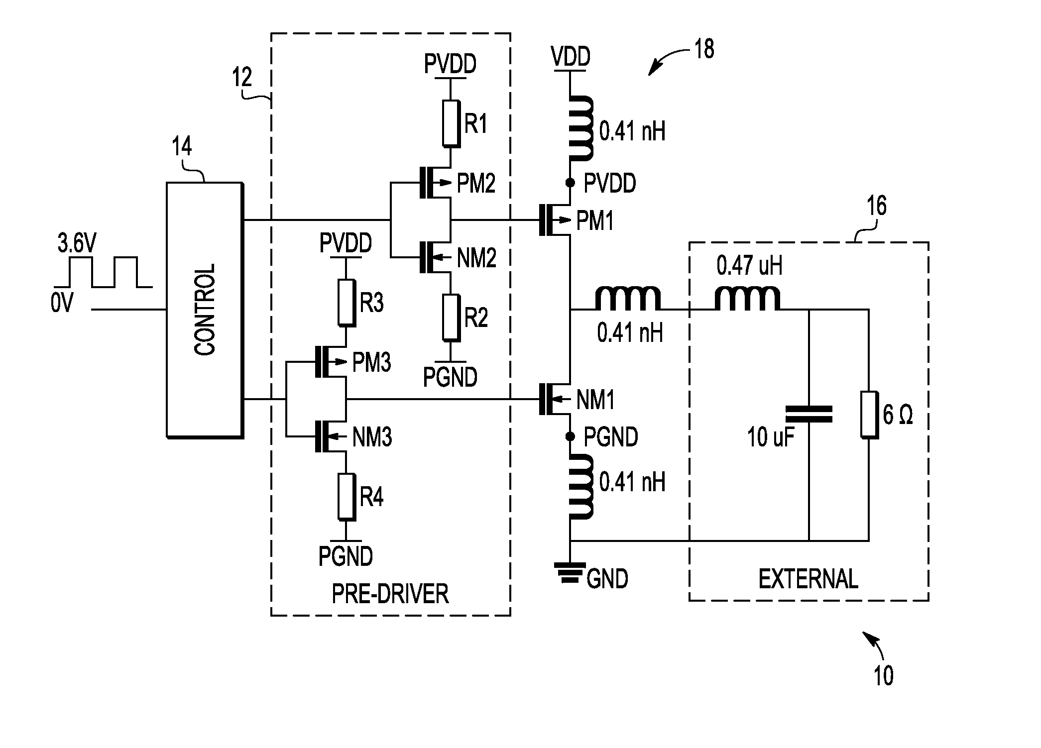
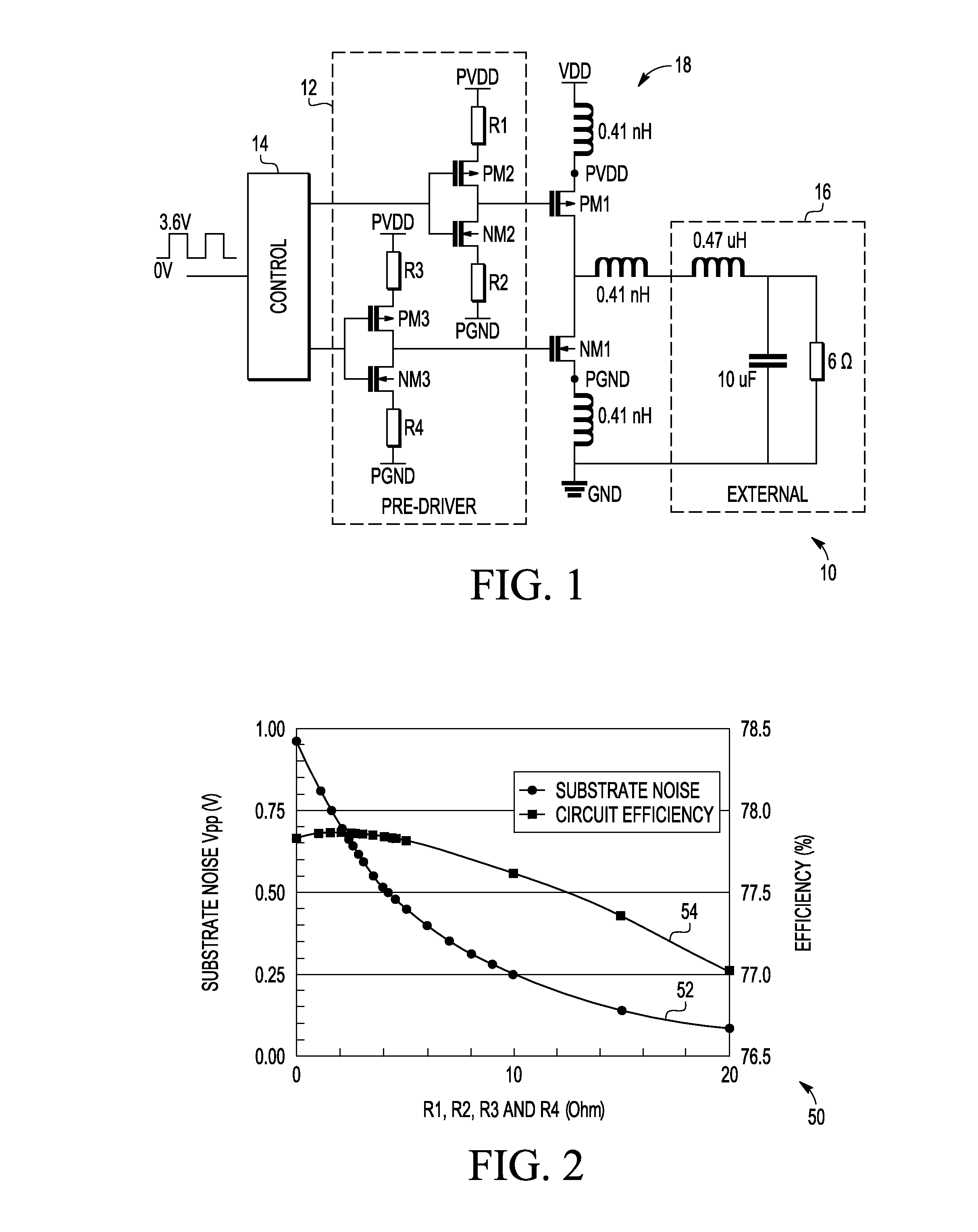
[0013]An aspect of the invention is a pre-driver circuit for driving a power switching circuit, the power switching circuit having a power device of a power stage of the power switching circuit. The pre-driver circuit includes a MOSFET having a source and a drain to drive with a drive current power devices of the power stage of the power switching device; and a resistor in series with the source of the MOSFET to adjust the drive current.

[0014]In an embodiment of the invention, the resistance of the resistor is selected to have a voltage across the resistor with the presence of the drive current to reduce the effective gate-source voltage (Vgs) and the drain-source voltage (Vds) of the MOSFET to adjust the drive current. The pre-driver circuit may comprise four MOSFET and a resistor in series with the source of the MOSFET to adjust the drive current, and the four MOSFET may comprise two NMOS and two PMOS. The pre-driver circuit may be part of a buck converter.

[0015]An aspect of the i...


PUM


Abstract

A MOSFET pre-driver circuit with highly adjustable drive current for a high frequency switching power MOSFET circuit decreases the peak of the drive current and power loss of the pre-driver while maintaining power loss of the power stage so that total power loss is decreased and circuit efficiency is increased. A resistor arranged in series with a source of the MOSFET of the pre-driver circuit is provided to adjust the drive current.

Description

BACKGROUND OF THE INVENTION[0001]The invention relates generally to high frequency power switching circuits and more particularly to a highly adjustable drive technique for high frequency power switching circuits.[0002]Power switching circuits, such as the power MOSFET and the insulated-gate bipolar transistor (IGBT), are commonly used in a variety of switching applications. However, when used in high frequency applications, the power switching circuits introduce a large amount of substrate noise and power / ground bounce. This leads to poor electro-magnetic compatibility (EMC). This can also degrade performance of sensitive analog blocks and increase electro-magnetic interference (EMI) within the chip.[0003]Dynamic switching loss of the power MOSFET also increases as the working frequency of the switching circuit increases. For relatively high frequency, i.e. for frequencies greater than 1 MHZ, power switching circuits that are integrated together in the same chip, the switching spee...

Claims


Application Information

Patent Timeline
IPC IPC(8): G05F1/10
CPCH02M1/08Y02B70/1466H02M3/1588Y02B70/10
Inventor YANG, JIANMAO, WEIWANG, CHUANZHENGZHAO, HONGWEIZHENG, JIANHUA
Owner FREESCALE SEMICON INC
Why Eureka
Try Eureka