Device and method for non-invasively evaluating a target of interest of a living subject

a living subject and target technology, applied in the field of non-invasive evaluation of living subjects, can solve the problems of unaddressed need in the art, raman spectroscopy is a purely biochemical technique, and yields limited information about tissue microstructure,

Active Publication Date: 2010-08-26
VANDERBILT UNIV +2
View PDF4 Cites 25 Cited by
  • Summary
  • Abstract
  • Description
  • Claims
  • Application Information

AI Technical Summary

Benefits of technology

[0014]In yet another aspect, the present invention relates to an optical probe for non-invasively evaluating a target of interest of a living subject. In one embodiment, the probe includes a casing with a first end and an opposite, second end. The casing of the probe is configured to be a handheld device. The probe further includes a first optical port, a second optical port, and a third optical port, where the first and second optical ports are located at the first end of the casing and the third optical port is located at the second end of the casing. The first and third optical ports define a first optical path betwe...

Problems solved by technology

However, Raman spectroscopy is a purely biochemical technique and yields limited information about the tissue microstructure.
Additionally, Raman si...

Method used


Image

  • Device and method for non-invasively evaluating a target of interest of a living subject
  • Device and method for non-invasively evaluating a target of interest of a living subject
  • Device and method for non-invasively evaluating a target of interest of a living subject

Examples


example 1

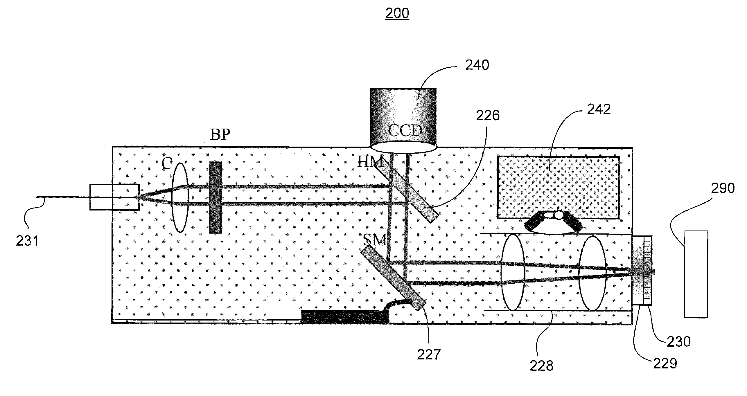
[0036]This example relates to a clinical, confocal Raman instrument, according to one embodiment of the present invention, with confocal imaging as well as bright-field imaging capability for the differential diagnosis of skin lesions by providing real-time, automated, non-intrusive spectral as well as spatial information about the tissue biochemistry as well as structure.

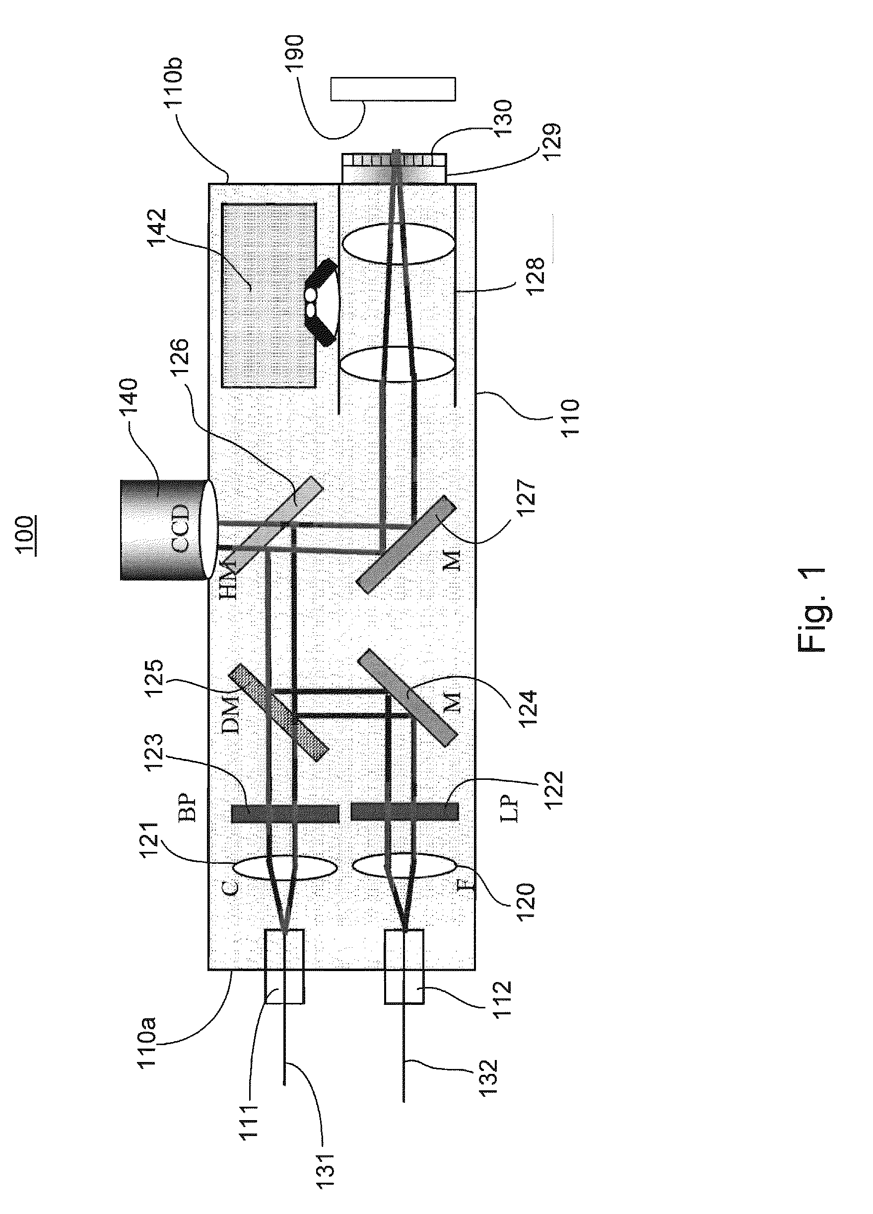
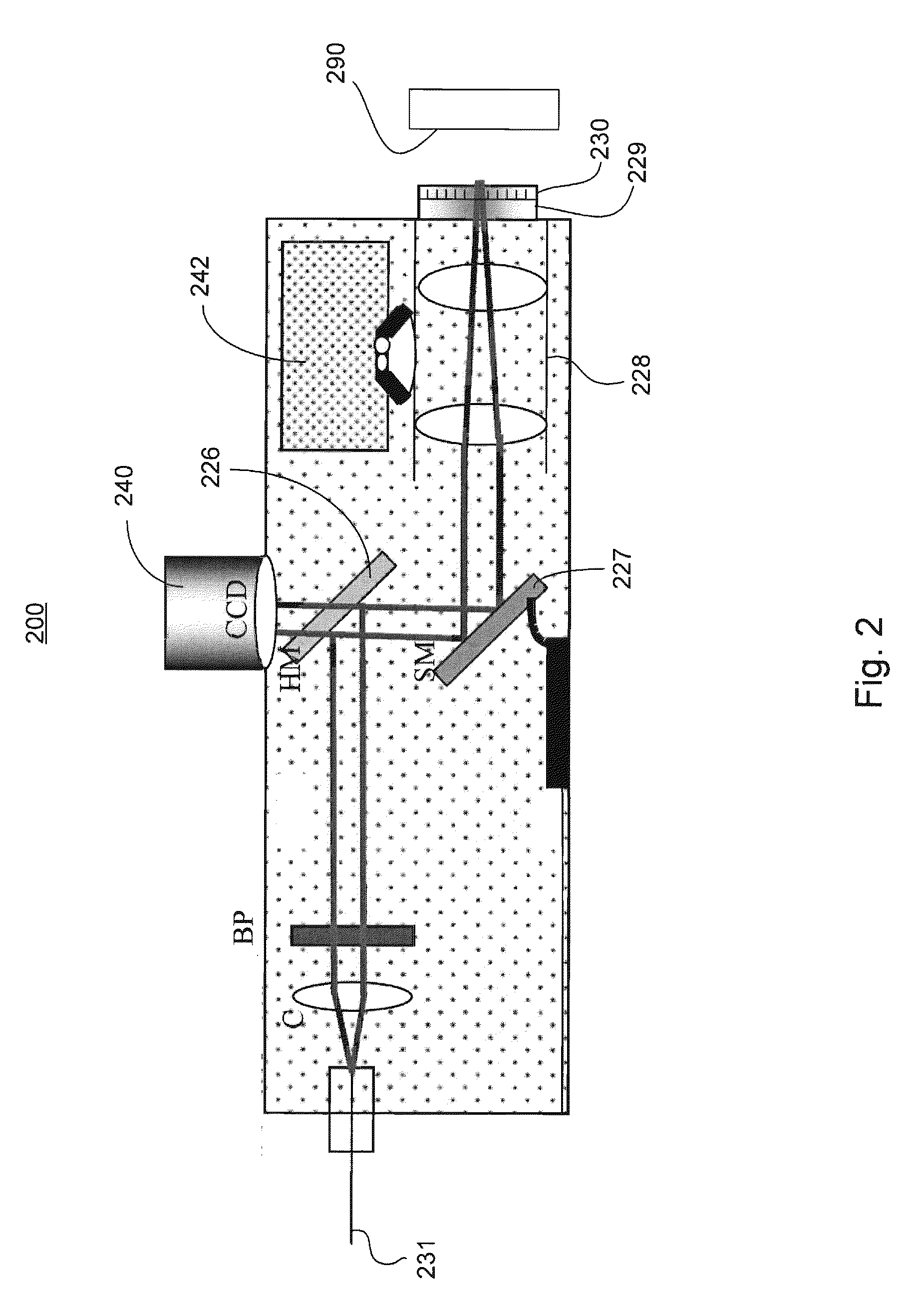
[0037]A compact handheld Raman probe with video imaging capability is first described, in connection with FIG. 1 of the drawings. Next, a handheld confocal imaging device at video rate is described, in connection with FIG. 2 of the drawings. An integrated handheld confocal Raman / scanning confocal imaging handheld device according to one exemplary embodiment of the present invention is then described in connection with FIGS. 3 and 4.

[0038]Now referring to FIG. 1, the dimensions of the probe 100 are determined by the microscope objective being used and the other commercially available mounts that are used for the opt...


PUM


Abstract

In one aspect, the present invention relates to a probe using integrated confocal reflectance imaging, confocal Raman spectroscopy, and gross spatial imaging for non-invasively evaluating a target of interest of a living subject. In one embodiment, the probe includes a casing with a first end and an opposite, second end, a first optical port, a second optical port, and a third optical port, where the first and second optical ports are located at the first end of the casing and the third optical port is located at the second end of the casing such that the first and third optical ports define a first optical path between them and the second and third optical ports define a second optical path between them, respectively, where each of the first and second optical paths has a first portion and a second portion, where the second portions of the first and second optical paths are substantially overlapped and proximal to the third optical port, and where the probe also includes a collimation lens, a coupling lens, an objective lens assembly, a first mirror, a second mirror, a third mirror, a band pass filter, a long pass filter, a scanning member, an electronic imaging device, and a focus control device, where the collimation lens, the band pass filter, and the second mirror are placed at the first portion of the first optical path, where the coupling lens, the long pass filter, and the first mirror are placed at the first portion of the second optical path, and where the third mirrors, the scanning member, and the objective assembly are placed at the overlapped second portion of the first and second optical paths.

Description

CROSS-REFERENCE TO RELATED PATENT APPLICATION[0001]This application claims the benefit, pursuant to 35 U.S.C. §119(e), of provisional U.S. Patent Application Ser. No. 61 / 155,404, filed Feb. 25, 2009, entitled “DEVICE AND METHOD FOR NON-INVASIVELY EVALUATING A TARGET OF INTEREST OF A LIVING SUBJECT”, by Anita Mahadevan-Jansen, David Dickensheets, and Chad Lieber, which is incorporated herein by reference in its entirety.[0002]Some references, which may include patents, patent applications and various publications, are cited and discussed in the description of this invention. The citation and / or discussion of such references is provided merely to clarify the description of the present invention and is not an admission that any such reference is “prior art” to the invention described herein. All references cited and discussed in this specification are incorporated herein by reference in their entireties and to the same extent as if each reference was individually incorporated by refere...

Claims


Application Information

Patent Timeline
IPC IPC(8): G01J3/44
CPCA61B5/0059A61B5/0064A61B5/0068A61B5/0075A61B5/444A61B5/445G01N2021/656G01J3/0208G01J3/021G01J3/0237G01J3/44G01J3/4412G01N21/65G01J3/02
Inventor MAHADEVAN-JANSEN, ANITADICKENSHEETS, DAVIDLIEBER, CHAD
Owner VANDERBILT UNIV
Why Eureka
Try Eureka