Ethernet link aggregation

a technology of ethernet link and aggregation, which is applied in the field of data processing systems, can solve the problems of large equipment that cannot refer to the ip address, cannot achieve the hash effect, and cannot achieve the distribution of load among links

Inactive Publication Date: 2010-08-26
IBM CORP
View PDF7 Cites 106 Cited by
  • Summary
  • Abstract
  • Description
  • Claims
  • Application Information

AI Technical Summary

Benefits of technology

[0008]In the method to determine the output port using only the MAC address, the MAC address needs to be fully distributed among packets. However, when the aforementioned equipment is used under a networ

Problems solved by technology

However, Ethernet operates in Layer 2 of the O.S.I. network layer protocol, so that although the method to refer to the MAC address is common, there is a great deal of equipment that cannot refer to the IP address.
However, when the aforement

Method used


Image

  • Ethernet link aggregation
  • Ethernet link aggregation
  • Ethernet link aggregation

Examples


Embodiment Construction

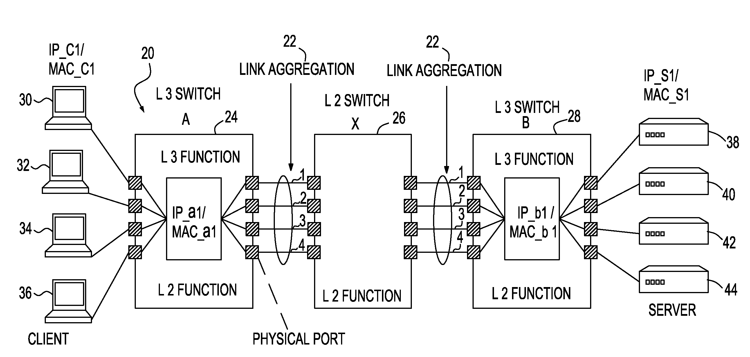
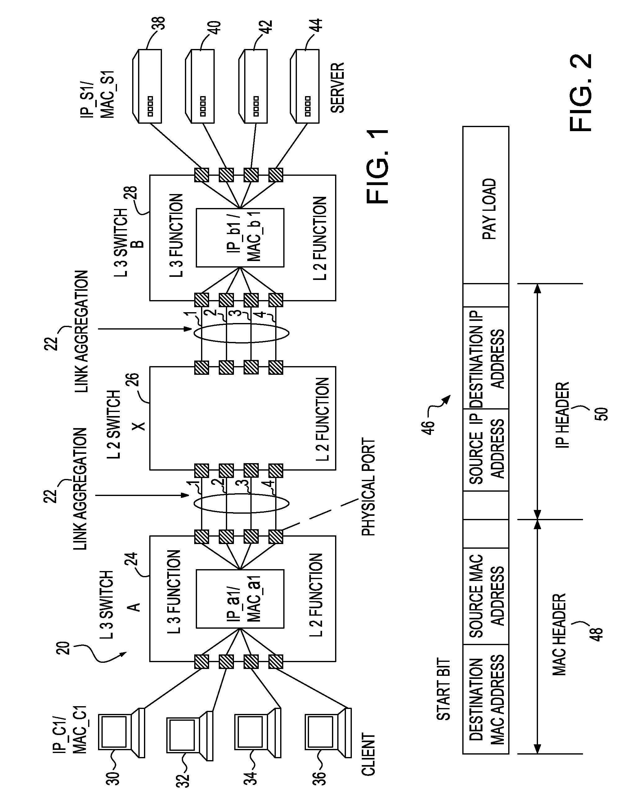
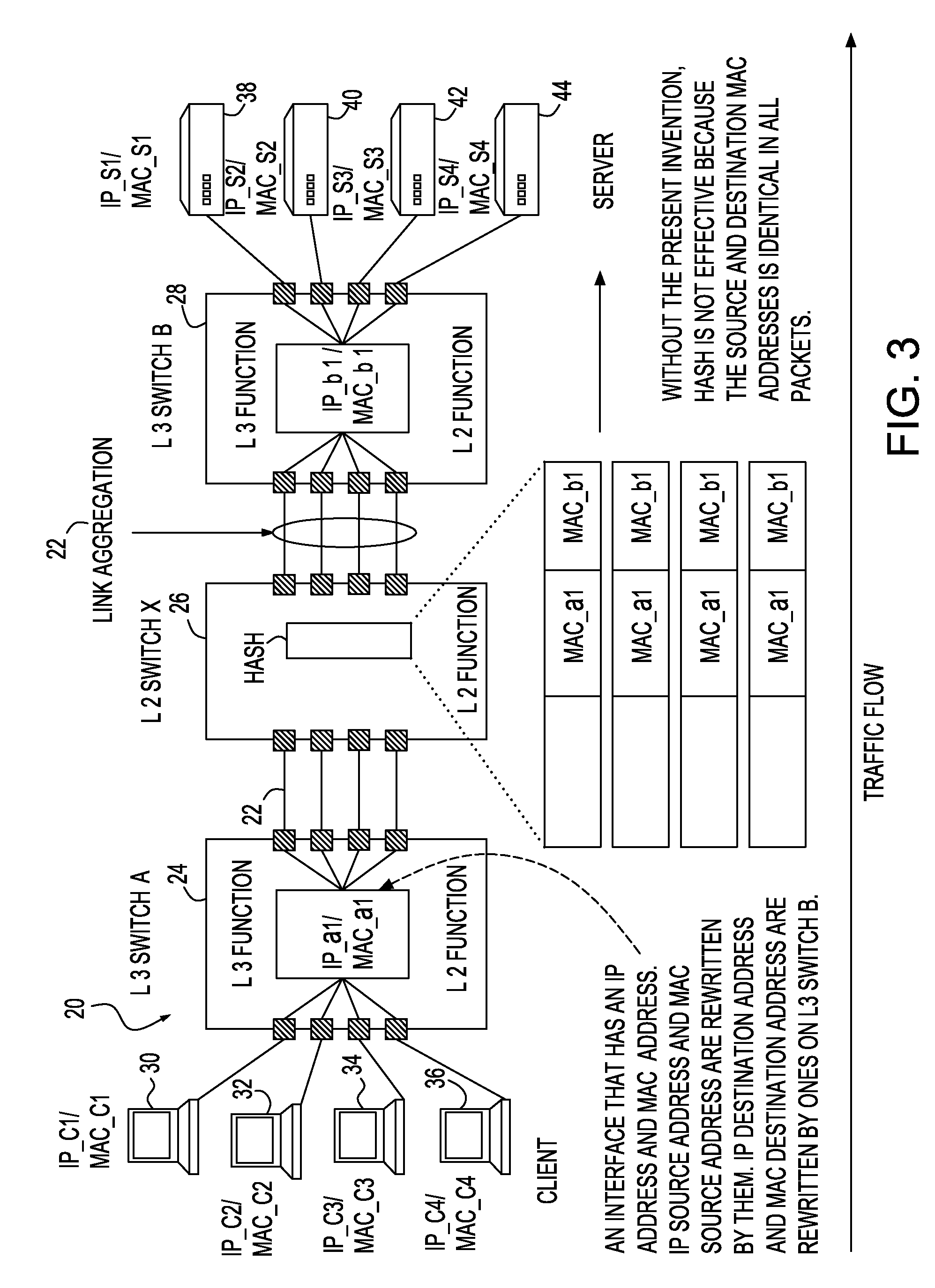
[0032]Referring to FIG. 1, there is shown a high level block diagram illustrating a network 20 which may be utilized to implement the method and system of the present invention. As illustrated, network 20 may be constructed utilizing a link aggregation 22 for transmitting data between switches 24, 26 and 28. Software which directs the flow of the packets can be a flow transmission controller (not shown) which may be provided at switches 24, 26 and 28 for storage in the switches via a variety of signal-bearing media which include, but not limited to storage media such as a floppy diskette. Switches 24, 26 and 28 can include a permanent storage medium (not shown) such as read-only memory (ROM) for storing the software and a temporary storage medium (not shown) such as random access memory (RAM) for supporting the implementation of the software.

[0033]Switches 24, 26 and 28 can be Ethernet switches. Each switch is networked with a plurality of devices where switch 24 is connected to dev...


PUM


Abstract

A system and method of transmitting data across a link aggregation group, the method comprises: receiving a packet sourced from a client having a MAC header and an IP header at an input port of a first upstream switch for transmission from the first upstream switch along a link aggregation and at least two down stream switches to a server, said MAC header having a Destination MAC address and a Source MAC address, and the IP header having a Source IP address and a Destination IP address; changing the destination MAC address from a down stream destination to another down stream destination; sending the packet through a first link aggregation to a first down stream switch; using a hash calculation for changing the Source MAC address of the packet in the first down stream switch to a new address; sending the packet through a second link aggregation to a second down stream switch having an address; and sending the packet from the second down stream switch to a server having a server address.

Description

BACKGROUND OF THE INVENTION[0001]1. Field of the Invention[0002]The present invention relates in general to data processing systems and more particularly to switching of data transmissions in a network.[0003]2. Background Information[0004]In a networking environment, it is typical that a plurality of devices will be linked together for the purpose of transmitting data from one device to another in the network. In a large network, it would be uneconomical to provide a specific data link connecting each device to each of the other devices in the network. In order to provide connectivity from each device to each of the other devices in the network in an efficient and economical manner, a plurality of methods have been developed.[0005]One known method of distributing data between devices within a network is through switches. Switches may be utilized within the network to receive data from a plurality of devices and distribute the data to a plurality of devices to reduce the amount of da...

Claims


Application Information

Patent Timeline
IPC IPC(8): H04L12/56H04L45/243H04L45/74
CPCH04L12/413Y02B60/33H04L45/745H04L45/245Y02D30/50H04L69/22H04L49/351H04W84/18H04L61/5092
Inventor SATO, MASAKAZUNAKAJIMA, SATOSHISUZUKI, KAZUNARI
Owner IBM CORP
Why Eureka
Try Eureka