Method for Determining a Set of Filter Coefficients for an Acoustic Echo Compensator

a filter coefficient and compensator technology, applied in the direction of transmission, signal processing, electric transducers, etc., can solve the problem that the acoustic echo compensator may become unnecessary after time-intensive re-adaptation for the current steering direction, and achieve the effect of improving the quality of echo compensation and low echo compensation

Active Publication Date: 2010-08-26
NUANCE COMM INC
View PDF16 Cites 108 Cited by
  • Summary
  • Abstract
  • Description
  • Claims
  • Application Information

AI Technical Summary

Benefits of technology

[0089]In this way, the provided sets of filter coefficients can be updated. In particular, the provided sets of filter coefficients which yield a low quality of echo compensation may be subsequently replaced by sets of filter coefficients yielding a better quality of echo compensation.
[0090]The ...

Problems solved by technology

A time intensive re-adaptation of the acoustic echo compen...

Method used


Image

  • Method for Determining a Set of Filter Coefficients for an Acoustic Echo Compensator
  • Method for Determining a Set of Filter Coefficients for an Acoustic Echo Compensator
  • Method for Determining a Set of Filter Coefficients for an Acoustic Echo Compensator

Examples


Embodiment Construction

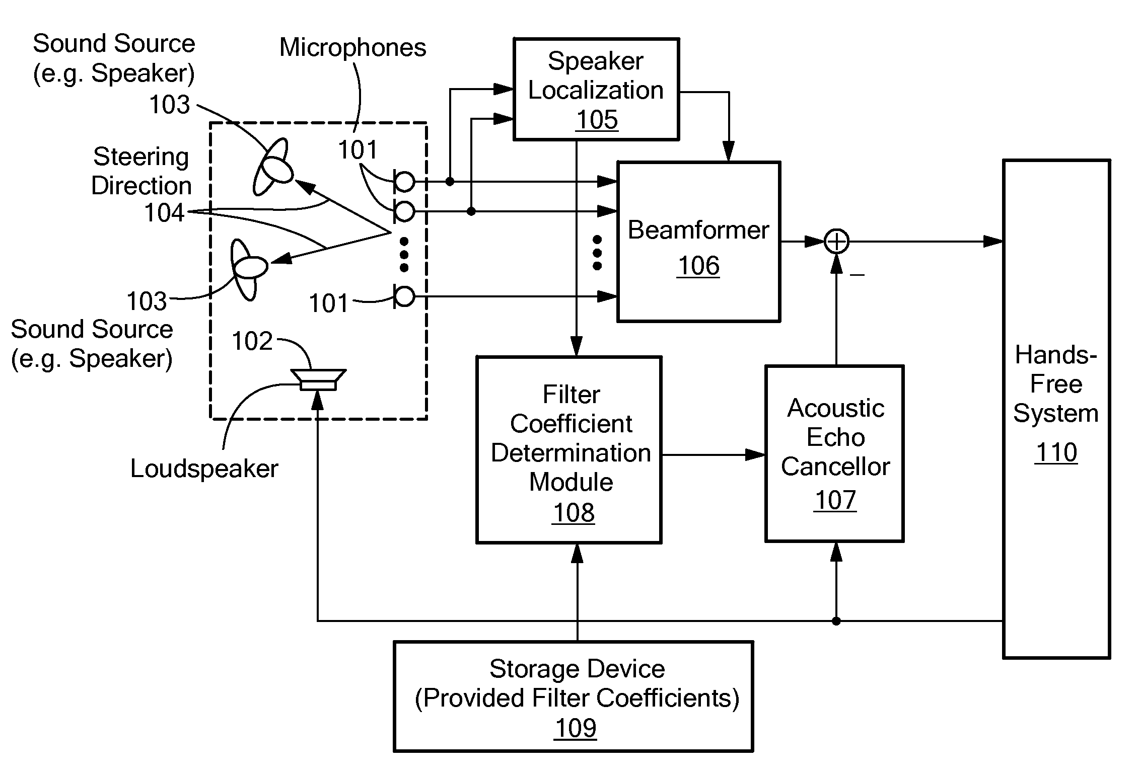
[0122]The system shown in FIG. 8 comprises a beamformer arrangement comprising a beamformer 806, localization module 805, a microphone array comprising a number of microphones 801 and an acoustic echo canceller 807. Furthermore a hands-free system 810, speaker 803, a loudspeaker 802 and two different steering directions 804 of the beamformer arrangement are shown.

[0123]In the embodiment shown in FIG. 8, only one acoustic echo canceller 807 is used that operates on a beamformed signal. Hence, a beamformer 806 yields a beamformed signal based on the microphone signals and the acoustic echo canceller 807 is used to model the loudspeaker-room-microphone-beamformer system.

[0124]The advantage of such a system, as shown in FIG. 8, is that only one acoustic echo canceller 807 is used which is computationally more efficient than performing echo compensation for each microphone signal independently. However, if the beamformer changes from one steering direction 804 to another, new steering di...


PUM


Abstract

The invention provides a method for determining a set of filter coefficients for an acoustic echo compensator in a beamformer arrangement. The acoustic echo compensator compensates for echoes within the beamformed signal. A plurality of sets of filter coefficients for the acoustic echo compensator is provided. Each set of filter coefficients corresponds to one of a predetermined number of steering directions of the beamformer arrangement. The predetermined number of steering directions is equal to or greater than the number of microphones in the microphone array. For a current steering direction, a current set of filter coefficients for the acoustic echo compensator is determined based on the provided sets of filter coefficients.

Description

PRIORITY[0001]The present application claims priority from European Patent Application No. 09002542.0 filed on Feb. 23, 2009 entitled “Method for determining a set of filter coefficients for an acoustic echo compensation means”, which is incorporated herein by reference in its entirety.TECHNICAL FIELD[0002]The present invention relates to a method for determining a set of filter coefficients for an acoustic echo compensator. In particular, the invention relates to a method for determining a set of filter coefficients for an acoustic echo compensator in a beamformer arrangement.BACKGROUND ART[0003]In a beamformer arrangement, acoustic signals are processed in such a way, that signals from a preferred direction are enhanced with respect to signals from other directions. This characteristic is in particular useful for speech signal processing, for example, for hands-free telephone sets or speech recognition systems in vehicles.[0004]For such systems, echo compensation is a basic issue....

Claims


Application Information

Patent Timeline
IPC IPC(8): H04B3/20
CPCG10L2021/02082H04M9/082H04R3/002H04R3/005H04R2430/20H04R1/406
Inventor BUCK, MARKUSSCHMIDT, GERHARDWOLFF, TOBIAS
Owner NUANCE COMM INC
Why Eureka
Try Eureka