Eureka AIR delivers breakthrough ideas for toughest innovation challenges, trusted by R&D personnel around the world.

Pulsation attenuation in systems with multiple compression elements

a technology of compression elements and attenuation, which is applied in the field of compression elements, can solve the problems of occupants of conditioned spaces being disruptive to the occupants of the space, damage and distraction of system components, and the compression element is a major source of pulsation induced nois

Inactive Publication Date: 2010-08-26
CARRIER CORP
View PDF3 Cites 5 Cited by
  • Summary
  • Abstract
  • Description
  • Claims
  • Application Information

AI Technical Summary

Problems solved by technology

In such vapor compression systems, the compressor is a major source of pulsation induced noise.
These pulsations transmitted through the refrigerant system can result in damage and distraction of the system components and can be disruptive to occupants of a conditioned space.
Screw compressor installations are particularly recognized to generate pulsation induced noise.
In these applications, pulsation induced noise can be particularly disruptive and bothersome, since the amplitude of pulsations may be additive from these multiple sources.
Many of these methods involve additional cost and complexity or have unproven effectiveness and reliability record.

Method used


Image

  • Pulsation attenuation in systems with multiple compression elements
  • Pulsation attenuation in systems with multiple compression elements
  • Pulsation attenuation in systems with multiple compression elements

Examples


Embodiment Construction

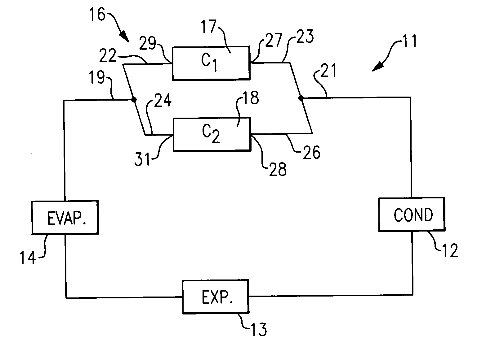
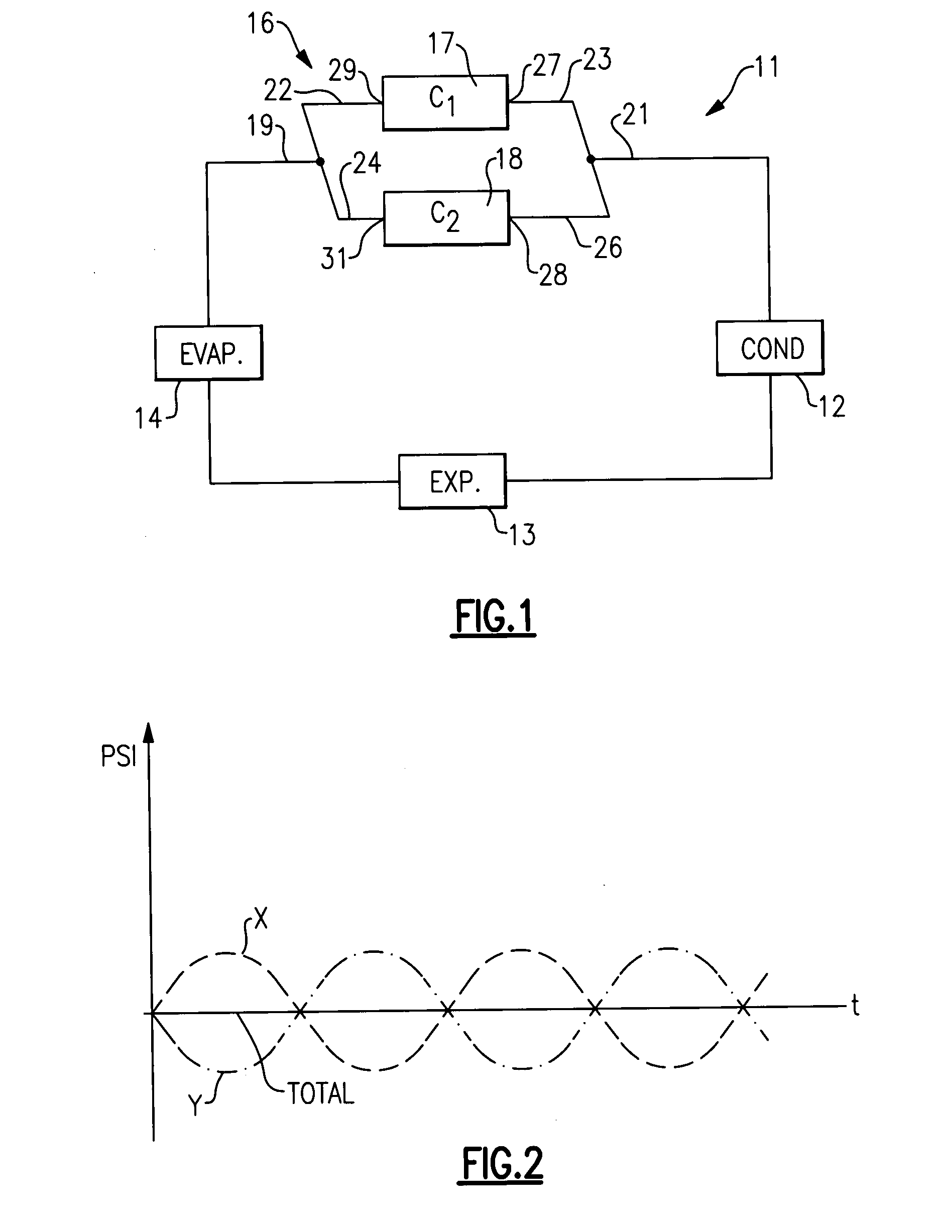
[0015]Shown in FIG. 1 is a schematic illustration of a basic vapor compression system 11 which includes, in a serial flow relationship, a condenser 12, an expansion device 13, an evaporator 14 and a compression system 16. In the cooling or refrigeration mode of operation, refrigerant flows serially from the compression system 16 to the condenser 12, the expansion device 13, the evaporator 14 and back to the compression system 16 which includes dual compressors 17 and 18 operating in tandem. In a heat pump mode of operation, the functions of the evaporator 14 and the condenser 12 are reversed. Obviously, by incorporation of appropriate flow control devices such as a four-way valve, the vapor compression system 11 can be made capable to run in both cooling and heating modes of operation.

[0016]As will be seen, the compression system 16 includes two compressors 17 and 18 arranged in parallel with a common suction manifold 19 and a common discharge manifold 21. The compressor 17 is conne...


PUM


Abstract

In compression systems having multiple sources of pulsation induced noise, provisions are made to reduce the noise by selectively varying the length of adjacent refrigerant lines leading to a common refrigerant manifold. Each of the refrigerant lines is associated with a particular noise source. The feature can be incorporated into compressors operating in parallel or in a single multi-rotor compressor having multiple suction or / and discharge ports. It is equally applicable to both discharge and suction ports.

Description

FIELD OF THE INVENTION[0001]This invention relates generally to compressors and, more particularly, to a method and apparatus for reducing pulsation induced noise generated by compression elements operating in parallel.BACKGROUND OF THE INVENTION[0002]Typical air conditioning, heat pump and refrigeration systems include at least one compressor for circulating a refrigerant throughout the system which includes at least a condenser (or a gas cooler), an expansion device and an evaporator. In such vapor compression systems, the compressor is a major source of pulsation induced noise. During operation, the compressor generates refrigerant pulsations propagating throughout the refrigerant system and contributes about fifty percent to the overall system sound level. These pulsations transmitted through the refrigerant system can result in damage and distraction of the system components and can be disruptive to occupants of a conditioned space.[0003]The types of compressors that are used i...

Claims


Application Information

Patent Timeline
IPC IPC(8): F04B39/00F25B41/00
CPCF04B39/0072
Inventor LIFSON, ALEXANDERTARAS, MICHAEL F.
Owner CARRIER CORP
Why Eureka
Eureka Blog
Learn More