Fuel supply device

a fuel supply device and fuel supply technology, which is applied in the direction of coupling device connection, positive displacement liquid engine, piston pump, etc., can solve the problems of disadvantageous requirements for four metal terminal members for each device, inability to use one of the coupler terminals, and space for locating the terminal attachment portions

Inactive Publication Date: 2010-08-26
MITSUBA CORP +1
View PDF6 Cites 10 Cited by
  • Summary
  • Abstract
  • Description
  • Claims
  • Application Information

AI Technical Summary

Benefits of technology

[0011]The present invention has an object of efficiently arranging terminals in a limited space while ensuring sealability in a wire-harness connecting portion of a fuel supply device. The present invention has another object of improving the easiness of placement of a grommet in a sealing structure using the grommet.
[0013]According to the aspect of the present invention, the terminal attachment portions are arranged alternately in two rows. As a result, a larger number of the terminal attachment portions can be arranged in a space having the same length as that of a conventional space. Moreover, an interval between the terminal attachment portions which are adjacent to each other in the same row can be increased as compared with a conventional one. Therefore, it becomes easy to insert the rubber grommet provided to the feeder wiring into the terminal attachment portion. Further, the number of types of the terminal members used as the power-feeding terminals can be reduced to two.
[0016]The rubber grommet is provided to the portion at which the power-feeding terminal and the feeder wiring are coupled, and a seal lip portion having a plurality of successively arranged concave portions and convex portions may be provided on an outer periphery of the rubber grommet. In addition, a point angle θ of each of the plurality of convex portions may be formed to be obtuse so as to easily remove the rubber grommet from a die at the time of molding. Moreover, a fluororubber having a high oil resistance may be used for the rubber grommet.
[0018]On the other hand, a fuel supply device according to another aspect of the present invention includes: an electric pump device driven by an electric motor; and a case member for housing and retaining the electric pump device therein, and is characterized in that: the case member includes a plurality of terminal attachment portions, in which a plurality of power-feeding terminals to be connected to feeder wirings of the electric motor are individually accommodated while being electrically insulated from each other; and each of the plurality of terminal attachment portions has a slit which allows to elastically enlarge an opening of each of the plurality of terminal attachment portions, at a fore-end thereof. As a result, for placing the feeder wiring in the terminal attachment portion, the insertion of the rubber grommet provided to the feeder wiring into the terminal attachment portion can be facilitated.

Problems solved by technology

Thus, one of the terminals of the coupler cannot be used.
Therefore, the metal member used for the terminal has a different shape for each of the terminals, and hence four metal terminal members are disadvantageously required for each device.
However, the space for locating the terminal attachment portions 102 is limited, and hence a large tapered portion cannot be formed over an opening portion of each of the terminal attachment portions 102.

Method used


Image

  • Fuel supply device
  • Fuel supply device
  • Fuel supply device

Examples


Embodiment Construction

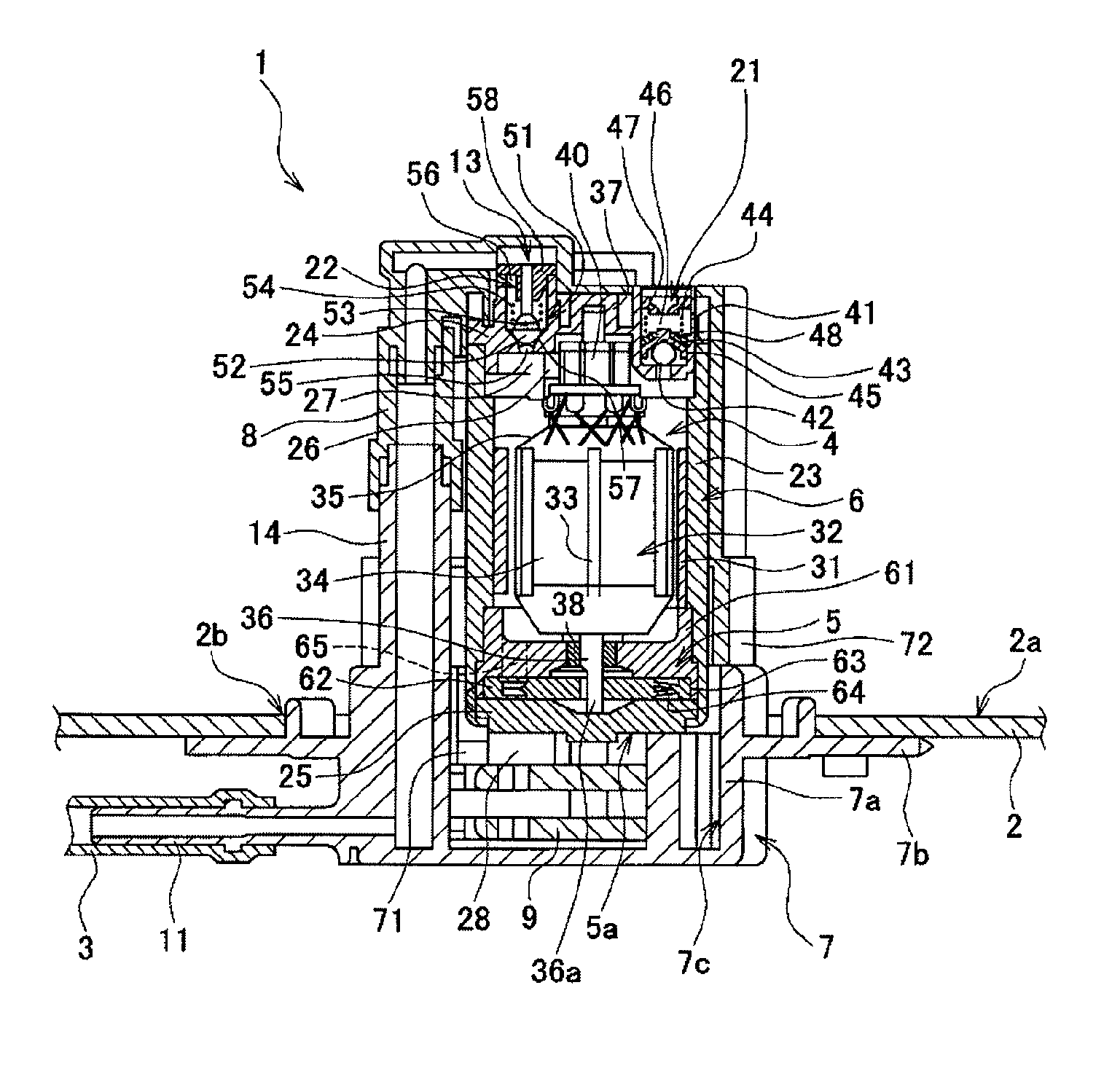
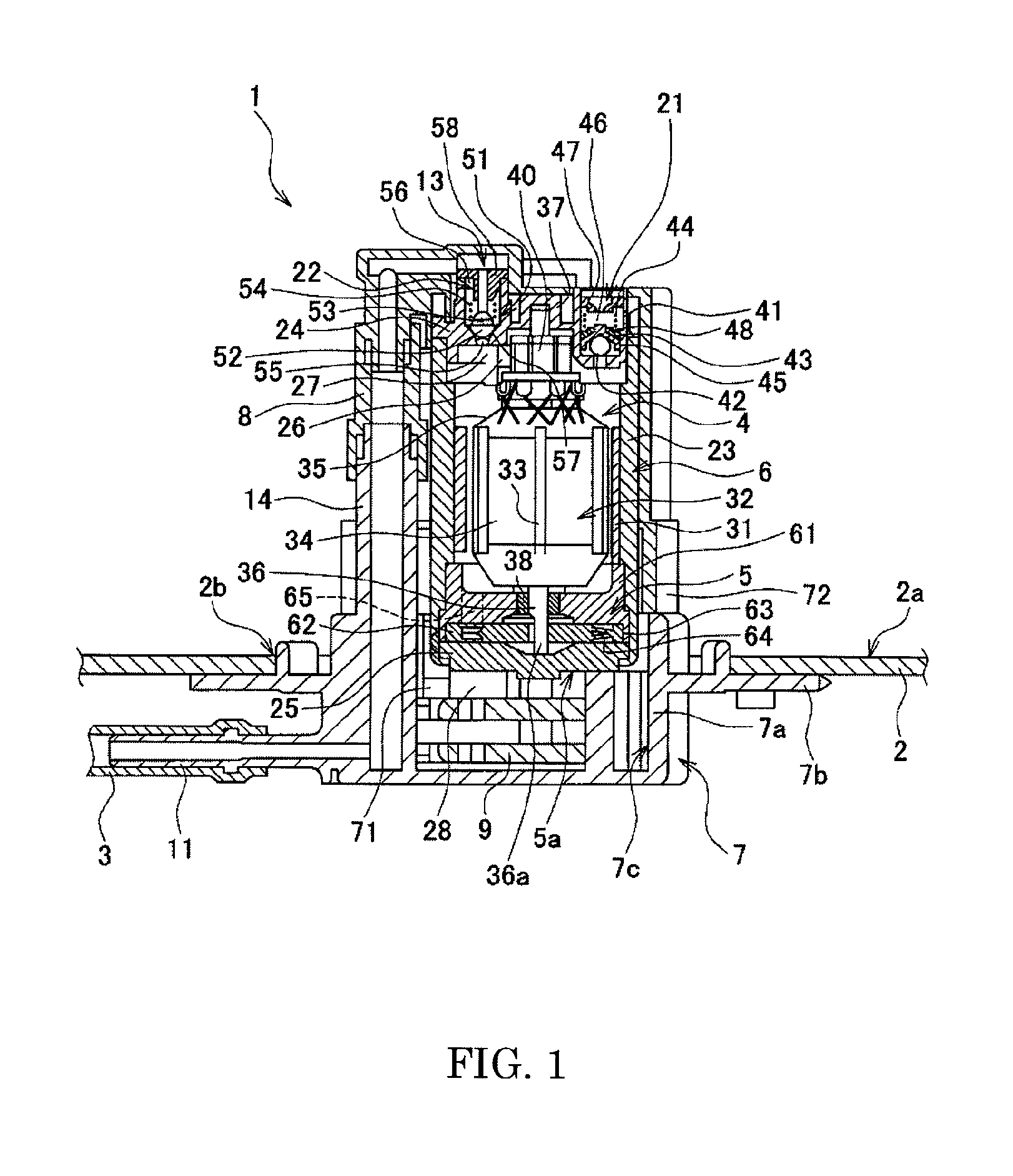
[0029]Hereinafter, exemplary embodiments of the present invention are described in detail with reference to the accompanying drawings. FIG. 1 is a sectional view illustrating a structure of a fuel supply device using an electric pump device, which corresponds to an embodiment of the present invention. A fuel supply device 1 illustrated in FIG. 1 is a device for a two-wheel motor vehicle. A fuel tank 2 stores a fuel obtained by mixing alcohol and gasoline in an arbitrary proportion. The fuel supply device 1 is mounted to the fuel tank 2 by being inserted upward from a bottom of the fuel tank 2. The fuel supply device 1 is connected to a fuel supply system (not shown) of an engine to supply the fuel to a fuel injection valve of the engine through a fuel pipe 3.

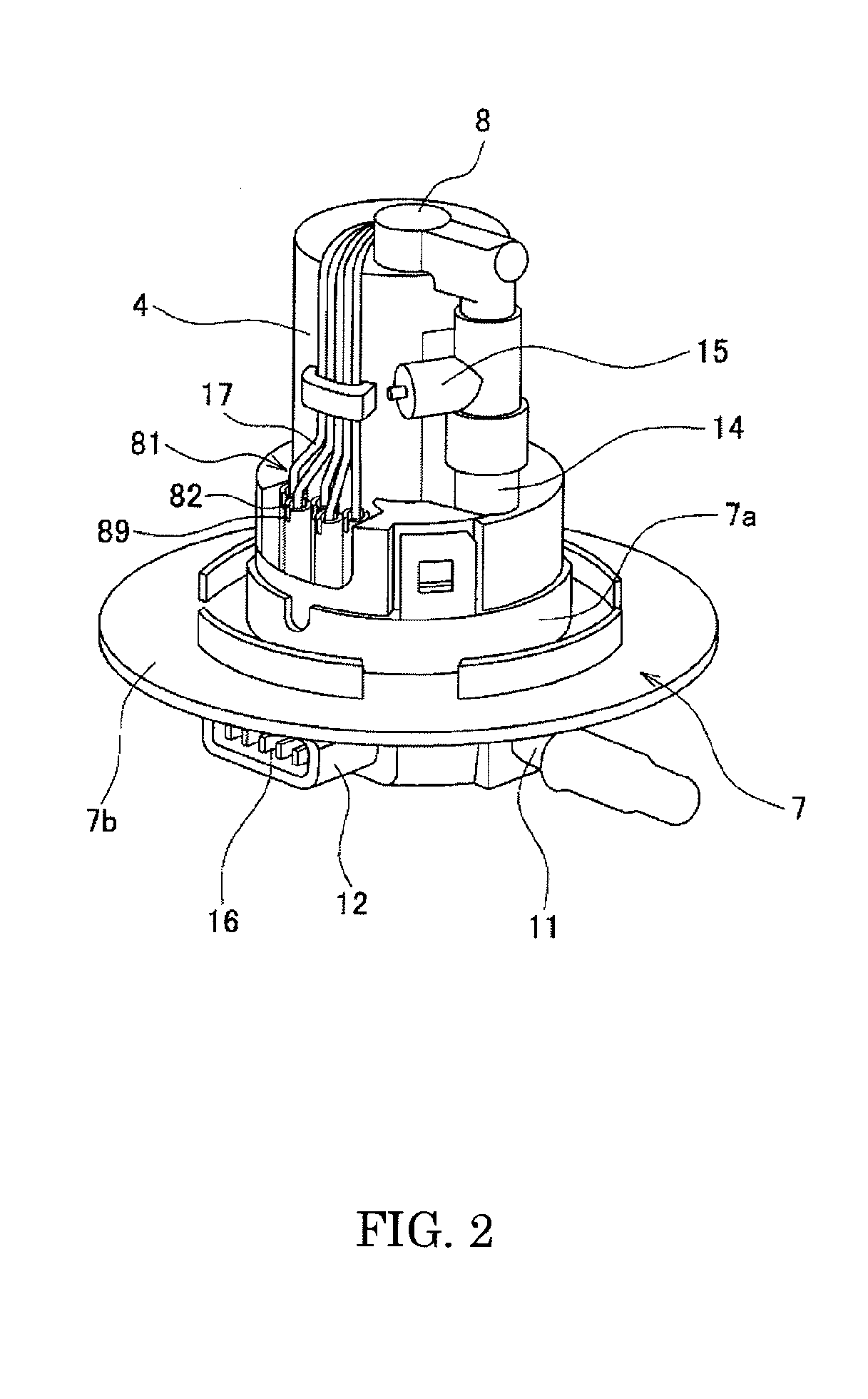
[0030]The fuel supply device 1 includes a pump assembly (electric pump device) 6 obtained by integrating an electric motor 4, a fuel pump (pump) 5, and the like. The pump assembly 6 is housed in a flange unit (case member) 7. An...


PUM


Abstract

Male terminals 83 are respectively provided in terminal attachment portions 82 formed on a flange unit 7. Female terminals 84 and grommets 85 are provided for a harness 17. A seal lip portion 86 to be fitted into each of the terminal attachment portions 82 is formed on each of the grommets 85. In the cylindrical terminal attachment portions 82, the male terminals 83 are individually accommodated while being electrically insulated from each other. The terminal attachment portions 82 are arranged alternately in two rows so that a line segment obtained by connecting the respective centers of openings of the terminal attachment portions is a polygonal line. The openings 87 are arranged to form the Olympic symbol. At a fore-end of each of the terminal attachment portions 82, slits 89 are provided. Owing to the slits 89, the opening 87 is likely to be enlarged when the rubber grommet 85 is inserted therethrough. As a result, the placement of the rubber grommet 85 is facilitated.

Description

BACKGROUND OF THE INVENTION[0001]1. Field of the Invention[0002]The present invention relates to a fuel supply device for a vehicle, which uses an electric pump device, in particular, a structure of a terminal connection portion of a wiring for feeding power to a motor, in a fuel supply device for a two-wheel motor vehicle.[0003]2. Description of the Related Art[0004]In recent years, a fuel pump module obtained by integrating a fuel pump, a pressure controller, a strainer, and the like is widely used as a fuel supply device for vehicles such as two-wheel and four-wheel vehicles, in view of the reduction of the number of components, the improvement of efficiency of an assembly operation, and the like. In the fuel pump module, an electric pump device (hereinafter, referred to simply as an “electric pump” as needed) driven by an electric motor is used as the fuel pump. The fuel pump is unitized together with the motor for driving the fuel pump and the like to be provided in a fuel tank...

Claims


Application Information

Patent Timeline
Patent Type & Authority Applications(United States)
IPC IPC(8): F04B17/03
CPCF02M37/103F04B17/03F04D5/002
Inventor HOMMA, BUNJIIKARUGI, TAKAONAKAMURA, TAICHIFUKUSHIMA, YASUNORIYANAGISAWA, TAKESHITORIYAMA, MASAYUKIYAMATE, NAOYUKI
Owner MITSUBA CORP
Why Eureka
Try Eureka