
Apparel

a technology of molded parts and linings, applied in the field of molded parts, can solve the problems of reducing wearer comfort, difficult manufacturing, and exclusive three-dimensional molded areas, and achieve the effect of reducing chafing

Inactive Publication Date: 2010-09-02
ADIDAS
View PDF85 Cites 29 Cited by
  • Summary
  • Abstract
  • Description
  • Claims
  • Application Information

AI Technical Summary

Benefits of technology

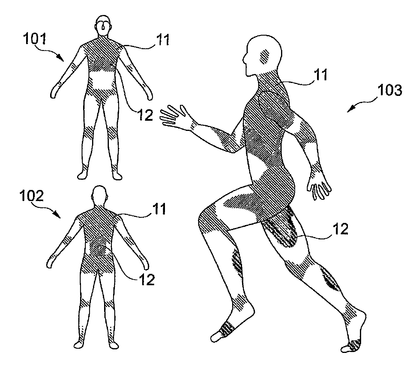
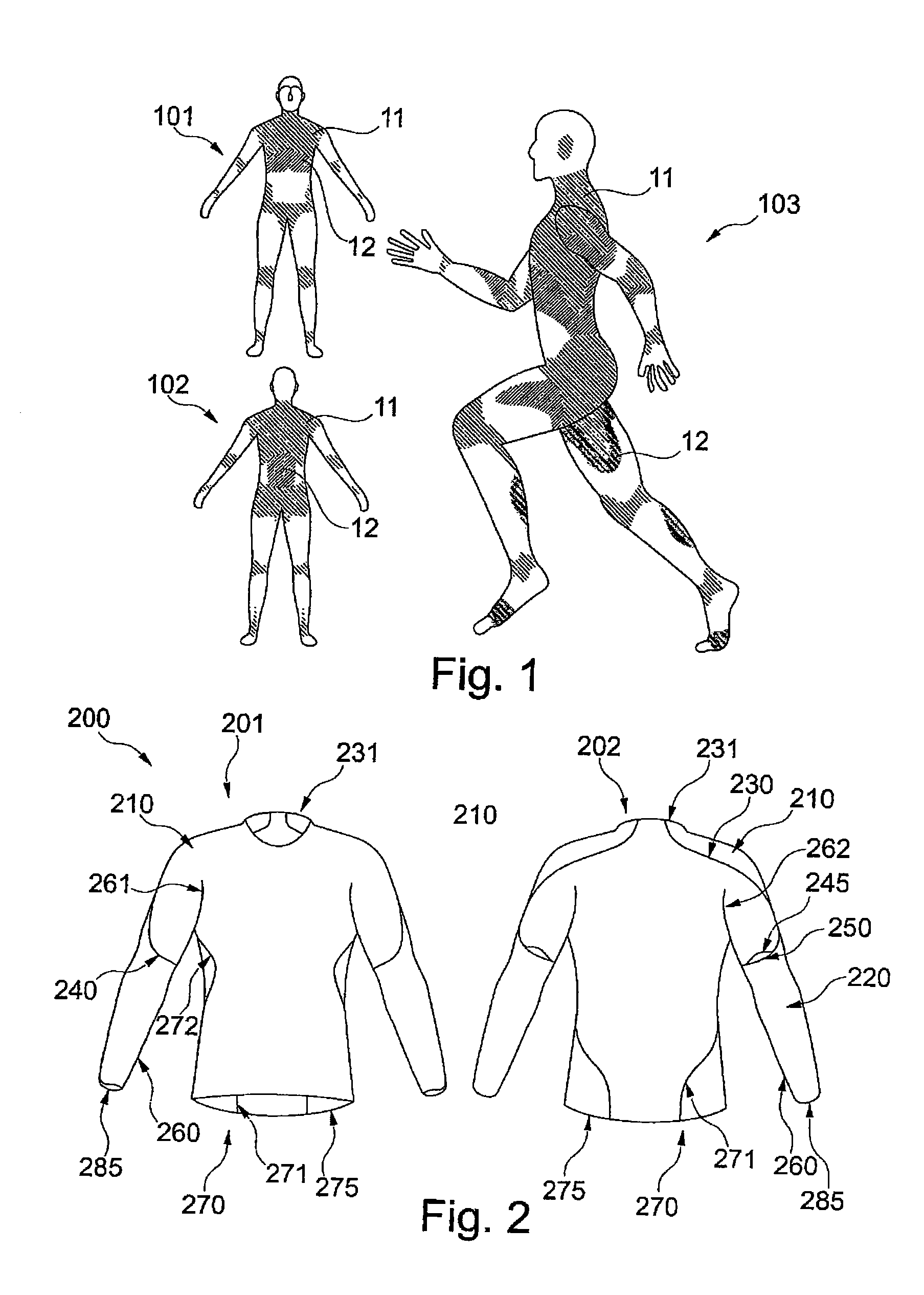
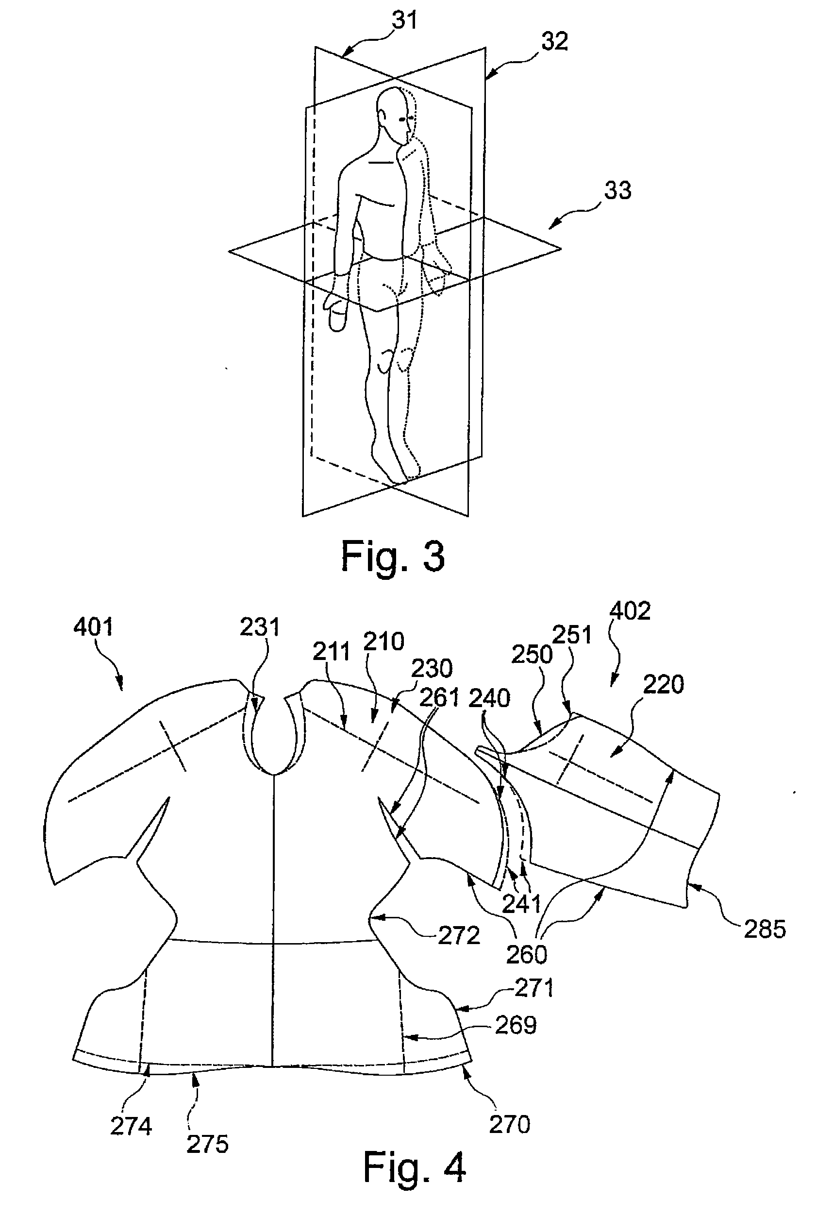
The present invention is a three-dimensional garment that reduces chafing and increases wearer comfort by minimizing stretching and compressing of the garment during movements. The garment includes a three-dimensional molded area formed by heat and a curved seam that connects the front and back areas of the garment. The seam is curved and does not run in sensitive areas of the body, such as the medial frontal plane or between the legs. The seam may intersect the medial frontal plane more than once and may be bonded by welding or gluing to minimize skin irritation. The garment may also have flexible inserts or sleeve edges with recesses for the bones to support a tight-fitting garment and avoid pressure and chafing on sensitive areas of the body.

Problems solved by technology

However, a good fit exclusively by three-dimensional molded areas is difficult to manufacture, at least for a tight fitting garment.
Namely, seams are necessary for the manufacture of the garment, even if they reduce the wearer comfort.
However, seams in these areas are most disturbing for athletes.
If in addition seams are located laterally at the upper body or between the legs, friction is further increased and may cause skin chafing.

Method used


Image

  • Apparel
  • Apparel
  • Apparel

Examples


first embodiment

[0109]FIG. 17 shows further embodiments of an article of sportswear in the area of the collar. a collar 1790 may be illustrated in front view 1701 and in back view 1702, which in contrast to the embodiment of FIG. 16 does not comprise a circumferential lower edge. Rather, on the back side of collar 1790 a padded area 1795 may be arranged whose upper edge may be flush with upper edge 1792. Upper edge 1792 has a shape similar to upper edge 1692 of FIG. 16 so that it forms an angle 1789, preferably an acute angle 1789, in the middle of the neck in front view 1701 and therefore may contour the clavicle bone.

[0110]Lower edge 1791 of padded area 1795 may comprise several curved sections and is again similar to the shape of lower edge 1691 of FIG. 16. In particular, lower edge 1791 may comprise section 1796 which may contour seventh cervical vertebra 1678 and / or first thoracic vertebra 1681 from view 1601 of FIG. 16, in order to avoid an irritation of these vertebras by the article of spor...

second embodiment

[0111]collar 1970 is illustrated in front view 1703 and back view 1704 of FIG. 17 which, in contrast to the embodiment of views 1701 and 1702, may comprise a circumferential collar 1798 which has a circumferential lower edge 1799. As can be recognized, angle 1789 may touch lower edge 1799.

[0112]FIG. 18 is a view of an embodiment of a stretchable area of an article of sportswear which may be arranged in the area of joints such as the elbow which require high freedom of movement. As can be recognized, a stretchable area 1820 in FIG. 18 may be formed by a bellow insert 1821. Insert 1821 may be manufactured from a textile material which differs from the material of the article of sportswear and which may in particular comprise elastic material. Insert 1821 may comprise plural folds of the textile material which unfold when the underlying joint bends. This may increase freedom of movements and wearer comfort of the article of sportswear since unfolding requires less force than stretching...


PUM

PropertyMeasurementUnit
temperatureaaaaaaaaaa
depthaaaaaaaaaa

Abstract

A garment which minimizes chafing includes a three-dimensional heat molded area and a seam connecting a front area of the garment with a back area of the garment. The seam may be curved and shaped to create a three-dimensionally shaped area.

Description

BACKGROUND OF THE INVENTION[0001]1. Field of the Invention[0002]The present invention relates to apparel which may provide high freedom of movement and / or wearer comfort. The present invention relates in particular to a garment with three-dimensionally formed areas.[0003]2. Background Art[0004]Apparel, in particular sportswear, frequently uses lightweight and elastic materials such as elastan which fit tighter to the body than conventional textile materials. Conventional garments impede movements due to their wide shape and require more effort for moving a part of the body due to the higher weight.[0005]On the other hand, a tight-fitting garment is constantly stretched and compressed during movement of the wearer, and therefore, can create wrinkles during wear. The creation of wrinkles reduces the freedom of movement of the wearer and can lead to wearout of the garment. Such disadvantages are particularly relevant for sportswear because the wearer, for example a runner, makes fast a...

Claims


Application Information

Patent Timeline
Patent Type & Authority Applications(United States)
IPC IPC(8): A41D1/00B28B1/14
CPCA41D13/0015A41D27/245B29L2031/4857A41H3/04A41H42/00B29C65/7435B29C66/0324B29C66/038B29C66/0384B29C66/20B29C66/301B29C66/729B29K2313/00B29L2031/485B29C65/00A41D31/185B29C65/02B29C66/71B29K2077/00B29K2067/00
Inventor STATTELMANN, MARTINALUDWIG, NINA MARIANOLAN, PAULINESIMON, ANDREA
Owner ADIDAS
Learn More