Refrigeration cycle apparatus

a technology of refrigerating cycle and apparatus, which is applied in the direction of domestic cooling apparatus, defrosting, application, etc., can solve the problems of reducing the efficiency of heat exchange at the evaporator, poor operation conditions of the cop, etc., and achieves shorter defrosting time, short time, and increased flow rate of refrigeran

Inactive Publication Date: 2010-09-02
PANASONIC CORP
View PDF18 Cites 30 Cited by
  • Summary
  • Abstract
  • Description
  • Claims
  • Application Information

AI Technical Summary

Benefits of technology

[0020]Based on such knowledge, the present inventors pursued intensive studies. As a result, they arrived at the fact that in the defrosting operation, it is possible to make the defrosting time shorter by increasing the total of the flow rate of the refrigerant at the outlet of the first compressor and the flow rate of the refrigerant at the outlet of the second compressor in accordance with melting of the frost than by keeping the rotation speeds of the first and second compressors each at a maximum rotation speed.
[0021]The main concept of the present invention is as follows. First, in the early stage of the defrosting operation, the defrosting operation is performed in a cycle in which the difference between the pressure of the refrigerant at the inlet of the compressor (the pressure at Point a1 in FIG. 11) and the pressure of the refrigerant at the inlet of the expander (the pressure at Point b1 in FIG. 11) is as small as possible and the enthalpy difference Δh1 is large. As the defrosting proceeds, the flow rate of the refrigerant is increased so as to cope with the variation in the state of the refrigeration cycle apparatus over time.
[0022]When thus configured, it is possible to perform the defrosting operation in an effective cycle from the beginning to the end of the defrosting operation, and finish the defrosting operation in a shorter time than when the rotation speeds of the first and second compressors each is kept at a maximum rotation speed from the beginning to end of the defrosting operation. In addition, power consumption also can be reduced.

Problems solved by technology

Accordingly, the COP is poor under operational conditions straying from ideal design conditions.
When the outside air temperature is closer to 0° C., frost starts to form on an evaporator, lowering extremely the efficiency of the heat exchange at the evaporator.

Method used


Image

  • Refrigeration cycle apparatus
  • Refrigeration cycle apparatus
  • Refrigeration cycle apparatus

Examples


Embodiment Construction

[0035]An embodiment of the refrigeration cycle apparatus of the present invention will be described with reference to the drawings.

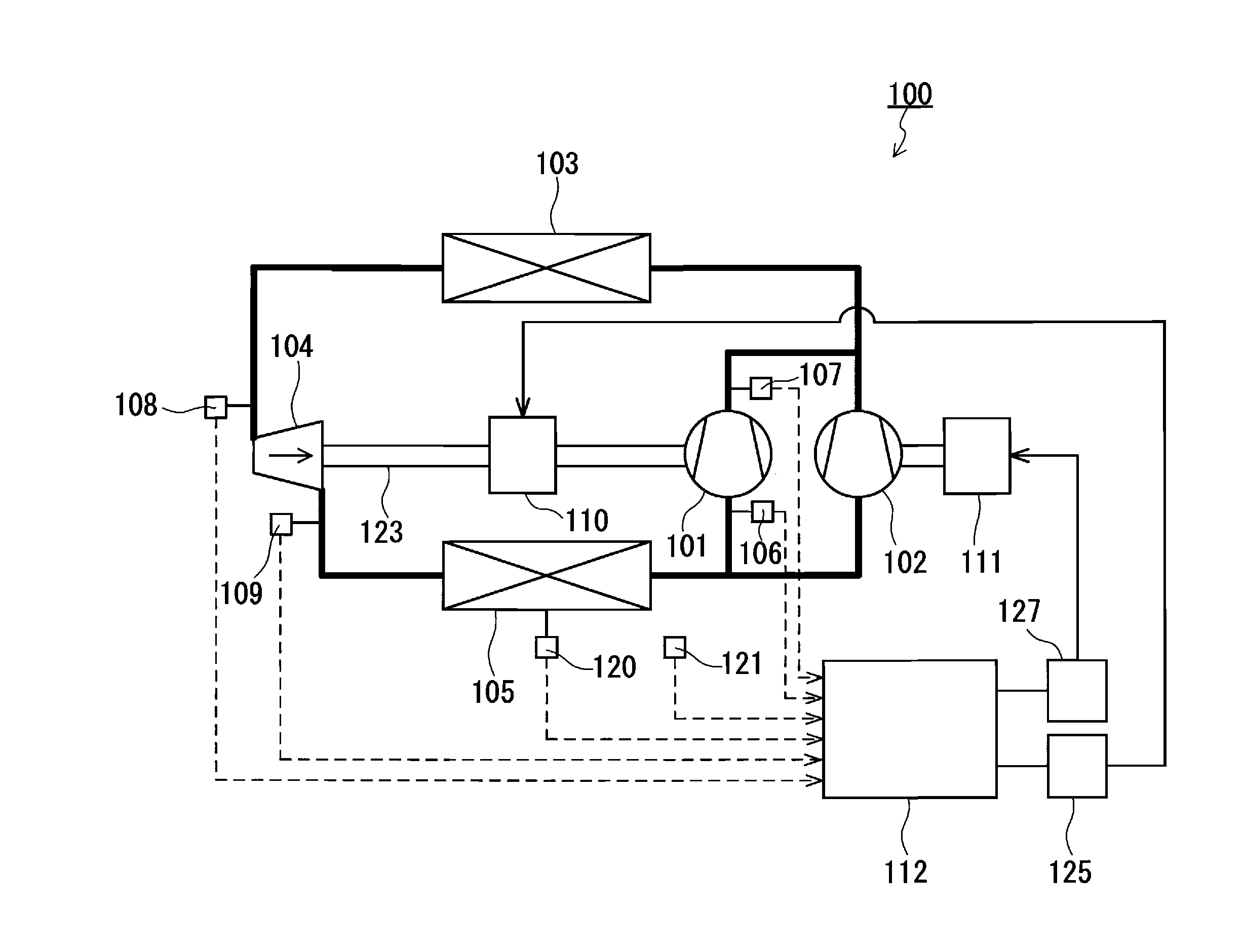
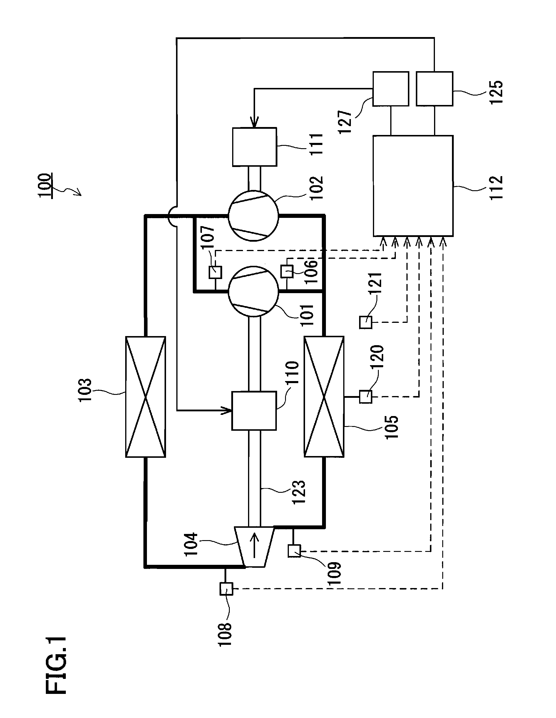
[0036]As shown in FIG. 1, a refrigeration cycle apparatus 100 of the present embodiment includes a first compressor 101 for compressing a refrigerant, a second compressor 102 provided in parallel with the first compressor 101 in a refrigerant circuit, a radiator 103 for cooling the refrigerant compressed by the first compressor 101 and the second compressor 102, an expander 104 for decompressing and expanding the refrigerant, and an evaporator 105 for heating the refrigerant expanded by the expander 104. These devices are connected by a pipe so as to form the refrigerant circuit. The refrigerant circuit branches off on a downstream side of the evaporator 105 so that the refrigerant is guided to each of the first compressor 101 and the second compressor 102. The branches of the refrigerant circuit are merged with each other on an upstream side of the radi...


PUM


Abstract

A refrigeration cycle apparatus 100 includes a first compressor 101, a second compressor 102 provided in parallel with the first compressor 101, a radiator 103 for cooling a refrigerant compressed by the compressors 101 and 102, an expander 104 for recovering power while expanding the refrigerant cooled by the radiator 103, an evaporator 105 for evaporating the refrigerant expanded by the expander 104, a rotation shaft 123 connecting the first compressor 101 to the expander 104 so that the first compressor 101 uses the power recovered by the expander 104, a controller 112 for executing a control including a step of increasing a flow rate of the refrigerant gradually during a defrosting operation in which frost formed on the evaporator 105 is melted by allowing the refrigerant having a high temperature to flow through the evaporator 105.

Description

TECHNICAL FIELD[0001]The present invention relates to a refrigeration cycle apparatus. Particularly, the present invention relates to a defrosting operation of a refrigeration cycle apparatus having an expander for recovering power from a refrigerant.BACKGROUND ART[0002]As shown in FIG. 9, there has been known a refrigeration cycle apparatus (JP 2001-116371 A) that is intended to improve COP (coefficient of performance) by connecting an expander 4 to a compressor 3 with a shaft so as to utilize the power obtained by the expander 4 for driving the compressor 3. Since the expander and the compressor are connected to each other with the shaft in this refrigeration cycle apparatus, the ratio of density ρe of the refrigerant at an inlet of the expander to density ρc of the refrigerant at an inlet of the compressor, which is ρe / ρc, always is constant (constraint of constant density ratio). Accordingly, the COP is poor under operational conditions straying from ideal design conditions.[000...

Claims


Application Information

Patent Timeline
Patent Type & Authority Applications(United States)
IPC IPC(8): F25D21/00F25B1/10
CPCF25B9/06F25B47/022F25B2309/061Y02B30/741F25B2400/14F25B2600/0253F25B2400/075Y02B30/70
Inventor YAKUMARU, YUICHITANIGUCHI, KATSUJIHONMA, MASAYA
Owner PANASONIC CORP
Why Eureka
Try Eureka