Dual clutch transmission

a transmission and clutch technology, applied in mechanical equipment, transportation and packaging, gearing, etc., can solve the problems of significant installation space, significant limitation of motor vehicle use, and unwanted extension of the needed installation length, and achieve the effect of small installation space, low cost and few components

Active Publication Date: 2010-09-02
ZF FRIEDRICHSHAFEN AG
View PDF10 Cites 3 Cited by
  • Summary
  • Abstract
  • Description
  • Claims
  • Application Information

AI Technical Summary

Benefits of technology

[0006]It is the task of the present invention to propose a dual clutch transmission based on the previously described type, in which power engaging gear ratio steps can be realized, cost-efficiently and with just few component parts, which need little installation space.

Problems solved by technology

To achieve the desired gear ratio steps in this known double clutch transmission, a vast number of gear planes are required, so that a significant installation space is needed.
This causes an unwanted extension of the needed installation length in axial direction, such that the use of this in a motor vehicle is significantly limited.

Method used


Image

  • Dual clutch transmission
  • Dual clutch transmission
  • Dual clutch transmission

Examples


first embodiment

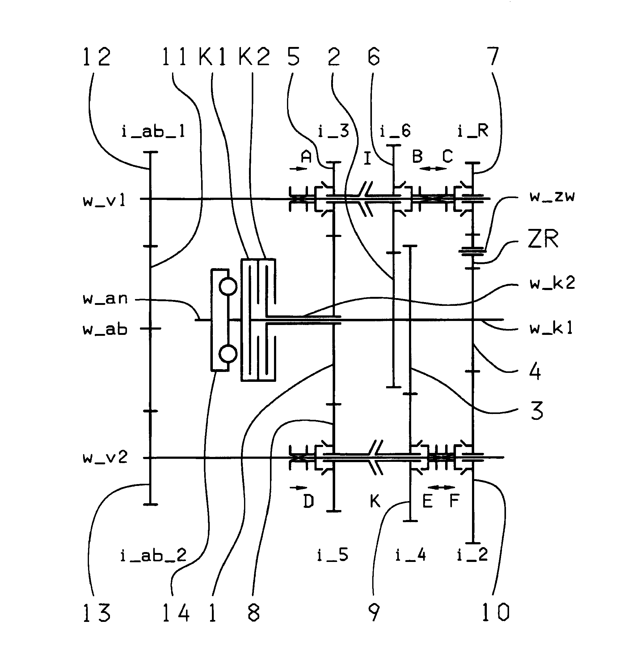
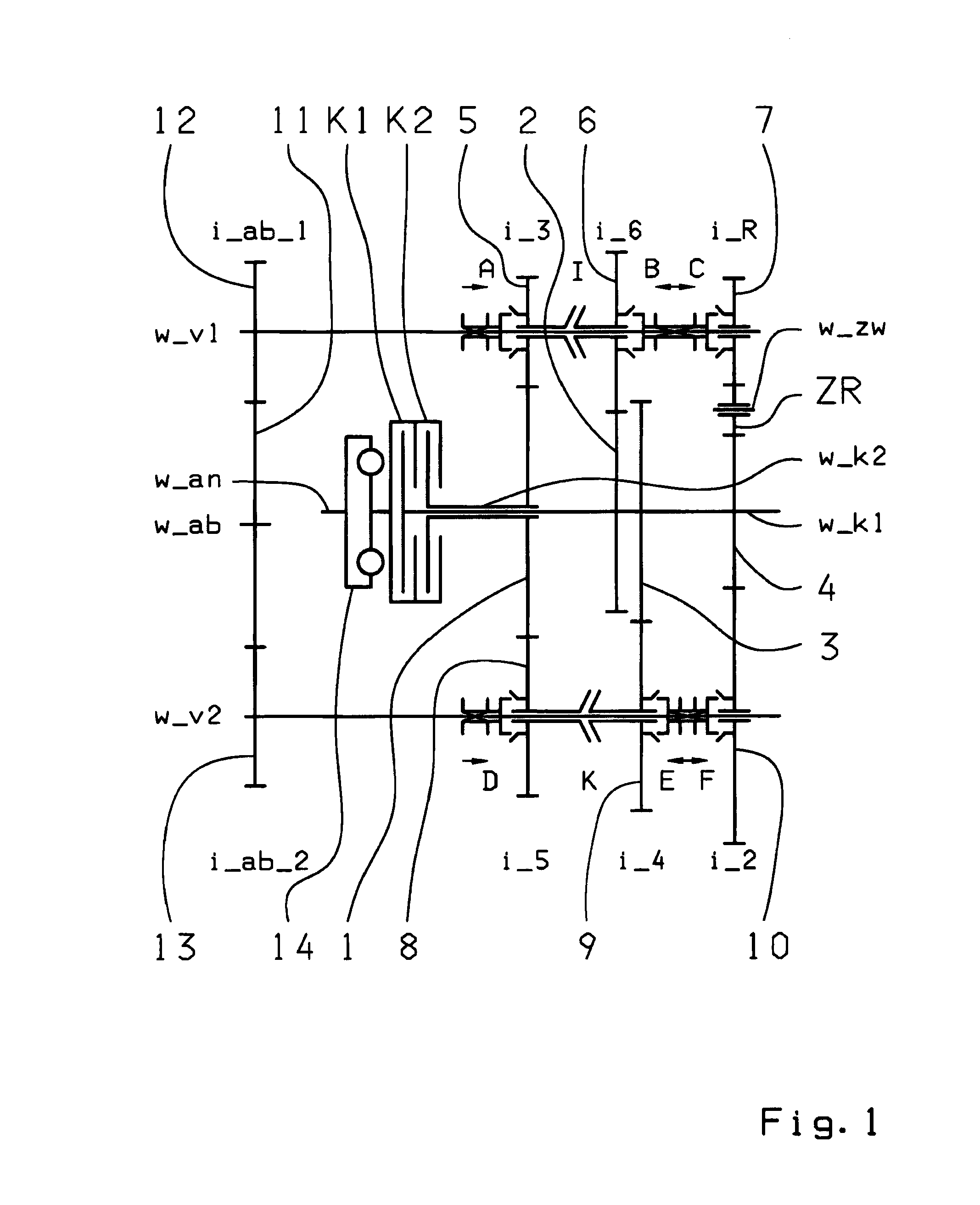
[0045]In the first embodiment, in accordance with FIG. 1, in the first gear plane, designed as a dual gear plane 5-8, the fixed gear wheel 1 of the second transmission input shaft w_K2 meshes with the idler gear wheel 5 of the first countershaft w_v1, and with the idler gear wheel 8 of the second countershaft w_v2. In the second gear plane, designed as a single gear plane, the fixed gear wheel 2 of the first transmission input shaft w_K1 meshes with the idler gear wheel 6 of the first countershaft w_v1. In the third gear plane, designed as a single gear plane, the fixed gear wheel 3 of the first transmission input shaft w_K1 meshes with the idler gear wheel 9 of the second countershaft w_v2. Finally in the fourth gear plane, designed as a dual gear plane 7-10, the fixed gear wheel 4 of the first transmission input shaft w_k1 meshes with the idler gear wheel 10 of the second countershaft w_v2, and with an intermediate gear ZR, whereby the intermediate gear ZR enables a reversal of ro...

third embodiment

[0047]In the third embodiment, in accordance with FIG. 5, and in the first gear plane which is a dual gear plane 5-8, the fixed gear wheel 1 of the second transmission input shaft w_K2 meshes with the idler gear wheel 5 of the first countershaft w_v1 the idler gear wheel 8 of the second countershaft w_v2. In the second gear plane, designed as a dual gear plane 6-9, the fixed gear wheel 2 of the first transmission input shaft w_K1 meshes with the idler gear wheel 6 of the first countershaft w_v1 with the idler gear wheel 9 of the second countershaft w_v2. In the third gear plane, designed as a single gear plane 7-3, the fixed gear wheel 3 of the first transmission input shaft w_K1 meshes with an intermediate gear ZR, whereby the intermediate gear enables the reversal of rotation for a reverse gear R1, R2, R3. The intermediate gear ZR is rotatably positioned on an intermediate shaft w_zw, whereby the intermediate shaft w_zw, in this example, is positioned parallel to the countershafts...

second embodiment

[0050]In the first and second embodiment, in accordance with FIGS. 1 and 3, dual action coupling devices B, C; E, F are positioned, in this example, on each countershaft w_v1, w_v2, whereby the dual action coupling device B, C, on the first countershaft w_v1, is positioned between the second gear plane, designed as a single gear plane 6-2, and the fourth gear plane, designed as a dual gear plane 7-10, and on the second countershaft w_v2, the dual action coupling device E, F is positioned between the third gear plane, designed as a single gear plane 3-9 and the fourth gear plane, designed as a dual gear plane 7-10. For each dual action coupling devices B, C; E, F, two single action coupling devices can also be provided. Via the coupling device B, the idler gear wheel 6 can be connected with the first countershaft w_v1, and via the coupling device C, the idler gear wheel 7 can be connected with the first countershaft w_v1. Via the coupling device E, the idler gear wheel 9 can be conne...


PUM


Abstract

A double clutch transmission with two clutches connected to a drive shaft and to one of two transmission input shafts. Fixed gears are coupled to the input shafts and engage idler gears. Several coupling devices connect the idler gears to a countershaft which have an output gear that couple gears of an output shaft such power shift forward gears and a reverse gear can be shifted. Two dual gear planes each comprising one fixed gear which is supported by an input shaft and two idler gears which are supported by a respective countershaft. In each dual gear plane at least one idler gear wheel can be used for at least two gears. Two single gear planes each comprise an idler gear wheel and a fixed gear wheel, so that at least one winding-path gear can be shifted via the shifting device and one winding-path gear via another shifting device.

Description

[0001]This application is a National Stage completion of PCT / EP2008 / 063420 filed Oct. 8, 2008, which claims priority from German patent application serial no. 10 2007 049 260.1 filed Oct. 15, 2007.FIELD OF THE INVENTION[0002]The present invention relates to a double clutch transmission for a motor vehicle.BACKGROUND OF THE INVENTION[0003]Known from the publication DE 103 05 241 A1 is a 6-speed or 7-speed dual clutch transmission. The dual clutch transmission comprises two clutches, each connected with their inputs to the drive shaft and their output to one of the two transmission input shafts. The two transmission input shafts are coaxially positioned towards each other. In addition, two countershafts are arranged to be axially parallel to the transmission input shafts, their idler gear wheels mesh with the fixed gear wheels of the transmission input shafts. Furthermore, coupling devices that are axially movable are positioned rotationally fixed manner on the countershaft to shift t...

Claims


Application Information

Patent Timeline
Patent Type & Authority Applications(United States)
IPC IPC(8): F16H3/16
CPCF16H3/006F16H3/093F16H2003/0807F16H2003/0826F16H2003/0931F16H2200/0026Y10T74/19233F16H2200/006F16H2200/0065F16H2200/0086F16H2200/0091Y10T74/19228F16H2200/0056
Inventor GUMPOLSBERGER, GERHARDWAFZIG, JUERGENREISCH, MATTHIASRIEGER, WOLFGANGDREIBHOLZ, RALF
Owner ZF FRIEDRICHSHAFEN AG
Why Eureka
Try Eureka