Comestible fluid rack with conduit routing system

a fluid rack and conduit technology, applied in the direction of dismountable cabinets, transportation and packaging, other domestic objects, etc., can solve the problems of unnecessarily long process, unfavorable installation of fluid racks, and affecting the quality of fluid storage, so as to increase the manufacturing cost of the rack system and reduce labor. the effect of installation

Inactive Publication Date: 2010-09-02
WHITE KEITH D
View PDF9 Cites 2 Cited by
  • Summary
  • Abstract
  • Description
  • Claims
  • Application Information

AI Technical Summary

Benefits of technology

[0006]The present system involves a way to route conduits between a container and a pump in a way that requires less labor to install, and requires only an insignificant increase in manufacturing costs of a rack system. In addition, there is no requirement to “attach” the conduits, so the system is without any ties. According, the possibility injury from ties and their sharp ends is eliminated, as well as the time and labor it take to install the ties.

Problems solved by technology

Since most racks have several containers, each with a conduit leading to a pump, it can be a problem to secure all of the conduits in an organized and easy fashion.
A problem with this system is the labor required to find a suitable attachment point on the rack, to position a conduit at this point, then to find and manipulate a tie around the rack and the conduit, and to finally tighten the tie.
With many containers and conduits, this can be an unnecessarily long process.
The ends of the ties can be left as it or cut, but in either case ends are left that tend to interfere with an installers operation and maintenance of the racks and containers.
In addition, the tends to snag on skin and clothing.
The ends are often cut in an attempt to minimize this the problem, but the cut end is often sharp and can more easily cut hands and arms, and tear clothing as an installer is installing the removing containers.

Method used


Image

  • Comestible fluid rack with conduit routing system
  • Comestible fluid rack with conduit routing system
  • Comestible fluid rack with conduit routing system

Examples


Embodiment Construction

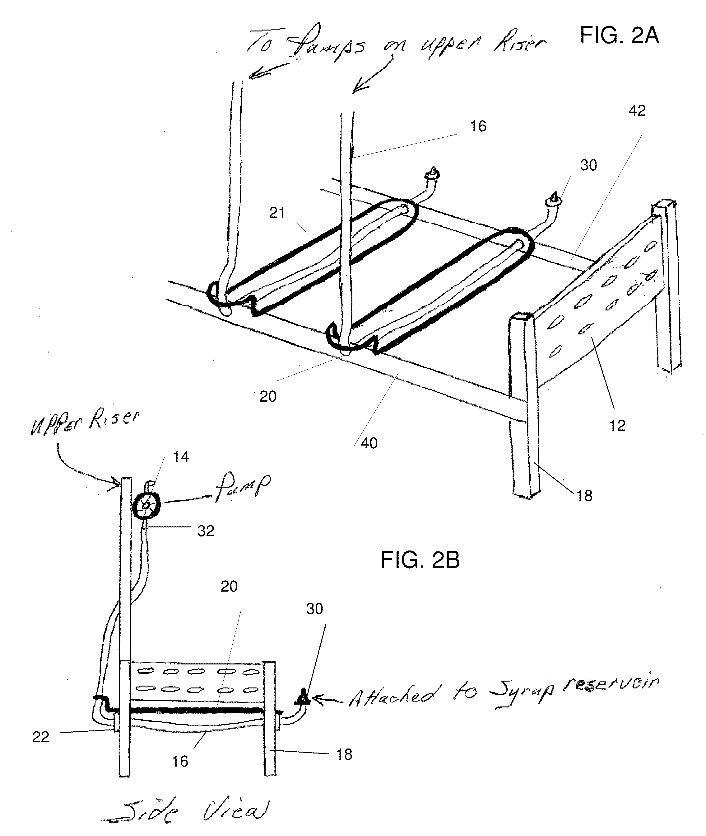
[0013]Reference is made to FIGS. 2A, 2B, 3, 4, 5, and 6.

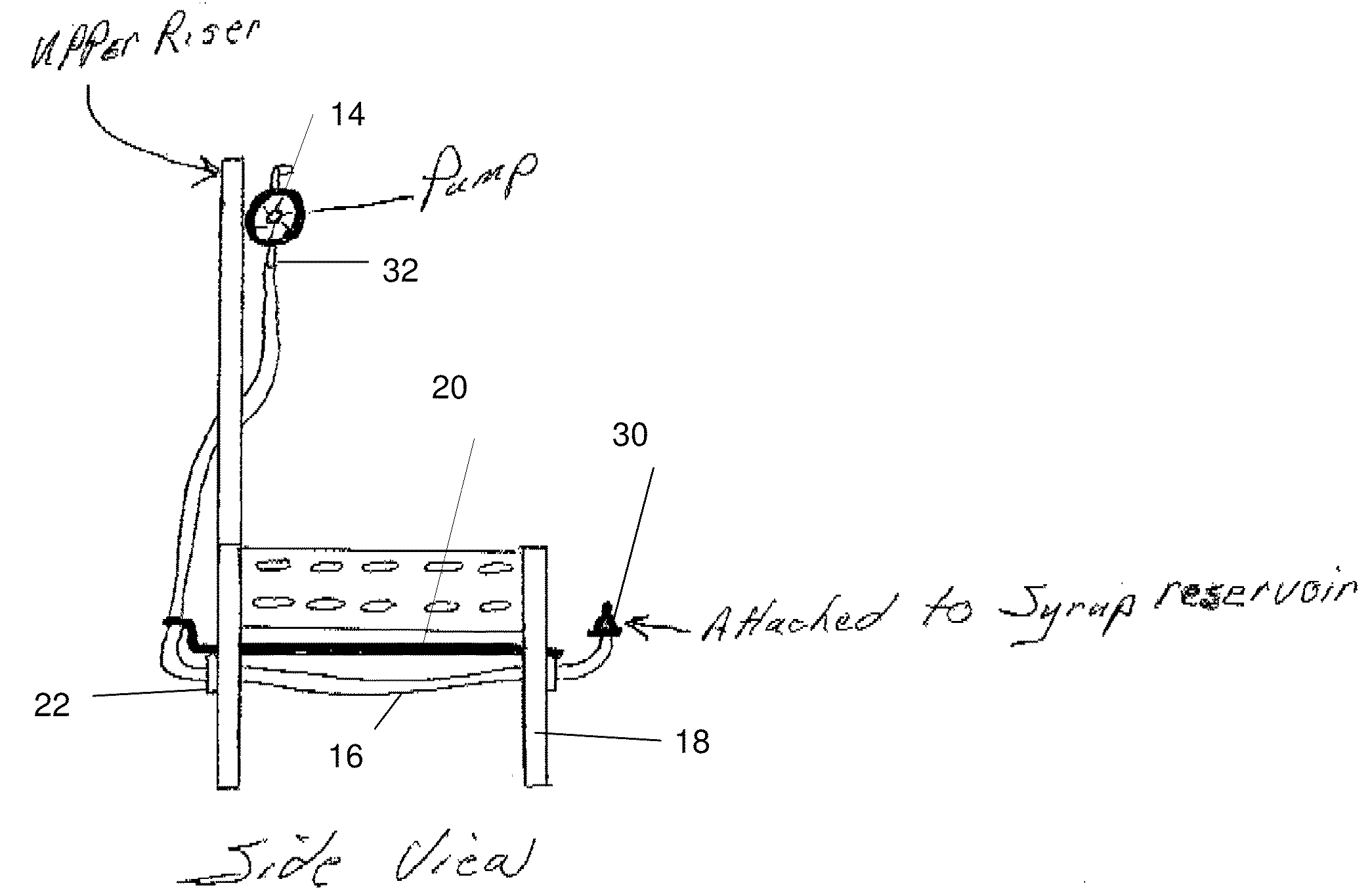
[0014]An embodiment is a rack for containers of comestible fluids comprising generally vertical upright members 18 with front and back rails 42, 40 extending generally horizontally between the upright members 18. Support rails 21 extend between the front and back rails and are constructed to provide at least one container station, where a container can be held. Several container stations are usually provided on the rack by having container stations side by side along the front rail, and having the stations stacked vertically.

[0015]One or more pump stations are provided for supporting enough pumps 14 to service all of the containers that may be mounted on the rack. The pump stations can be an any convenient location, such on a side panel, or a panel extending up from the back of the rack.

[0016]Conduits 16 extend between a first end 30 and a second end 32 of the conduit. The first end of a conduit is at one of the container stati...


PUM

PropertyMeasurementUnit
lengthaaaaaaaaaa
timeaaaaaaaaaa
dimensionaaaaaaaaaa

Abstract

A rack for comestible fluids with conduit portals in front and rear rails for passage and support of the conduits passing from the fluid container to the pump.

Description

CROSS REFERENCE TO RELATE APPLICATIONS[0001]This application claims priority from U.S. Provisional Patent Application 61 / 021416, filed 28 Feb. 2008.BACKGROUND OF INVENTION[0002]Racks of many different configurations are currently available in the food and beverage industry. An example of a fluid container commonly used in the food and beverage industry is the “bag-in-box” container, whereby a comestible fluid (such as a beverage, a syrup or other beverage concentrate, and the like) is contained within a bag enclosed within a box for support. A tap and pump is often employed to extract the comestible fluid from the bag. For example, a tap can be positioned toward the bottom of the bag to enable the fluid to be more completely removed from the bag via a conduit between the tap and pump. Pumps, one for each of the installed containers are mounted on the rack, for example on panels or horizontal rails one one or both ends of the rack. An exemplary rack configuration has generally horizo...

Claims


Application Information

Patent Timeline
Patent Type & Authority Applications(United States)
IPC IPC(8): A47F5/00
CPCA47B47/0083A47B81/00B67D3/0087B67D1/0892A47J47/01
Inventor WHITE, KEITH D.
Owner WHITE KEITH D
Why Eureka
Try Eureka