
Bit Retention Device

a technology of bit retention device and power or hand tool, which is applied in the direction of chucks, mechanical equipment, manufacturing tools, etc., to achieve the effects of reducing or eliminating the infiltration of dust and debris, facilitating removal, and operating more smoothly

Active Publication Date: 2010-09-02
BLACK & DECKER INC
View PDF121 Cites 41 Cited by
  • Summary
  • Abstract
  • Description
  • Claims
  • Application Information

AI Technical Summary

Benefits of technology

[0003]Bit retention devices for power and hand tools have become increasingly common, especially as the need and desirability of wider versatility and the use of power tools and hand tools has increased. Such bit retention devices allow the hand or power tool to be used with any of a number of interchangeable bits. This, in turn, has resulted in demands for greater speed, convenience, and ease for insertion and removal of tool bits from the bit retention device.
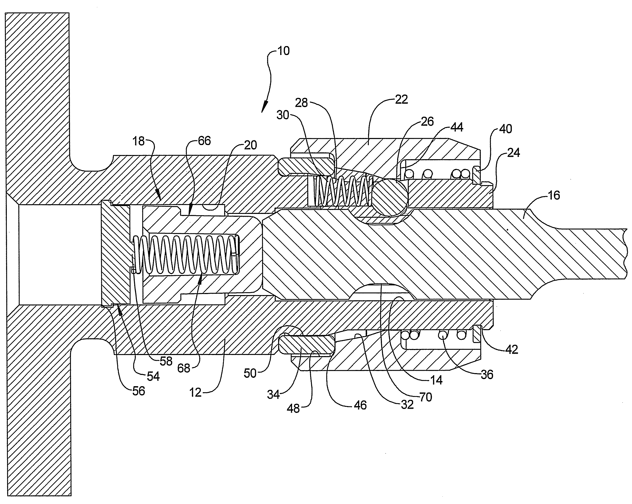
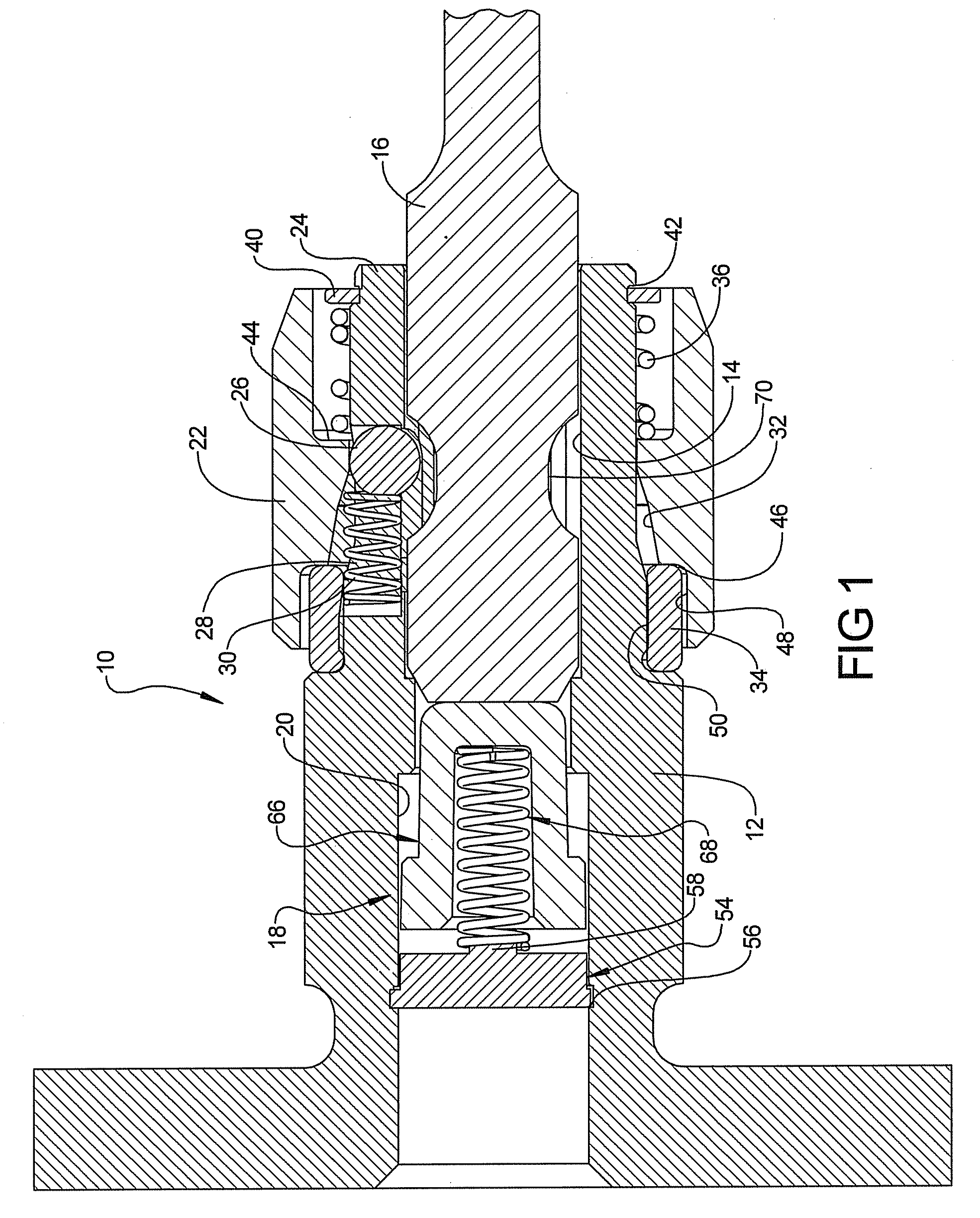
[0046]As shown in FIG. 16, the bit retention device 10 can further be provided with an over-molded magnetic nose cover 110. The over-molded magnetic nose cover 110 can include a nose magnet 90 constructed generally as described above. A plastic cover 112 can be over-molded on the nose magnet 90 or alternatively, the nose magnet 90 can be inserted into the cover 112. The cover 112 can be made of plastic or elastomer and is designed to prevent the knurled metal sleeve 22 from marring the work material. A slight interference between the cover 112 and the sleeve 22 may retain the cover onto the shaft or, alternatively, a wrap around portion or adhesives can be utilized for securing the cover 112 onto the actuator sleeve 22. In assembled condition as illustrated in FIG. 16, the nose magnet 90 will attract a fastener to the bit 16 hold the fastener in place. Furthermore, the cover portion 112 protects the work piece from being marred while a fastener is being inserted. It should be noted that the magnet 90 may also retain the cover onto the shaft to provide a cover 112 and magnet 90 that can be easily removed as desired by the user.

Problems solved by technology

Although this basic design has performed well, such conventional quick-release bit retention devices frequently require the operator to actuate a sleeve, collar, or other component part during both the insertion and the removal of the tool bit.

Method used


Image

  • Bit Retention Device
  • Bit Retention Device
  • Bit Retention Device

Examples


Embodiment Construction

[0026]Example embodiments will now be described more fully with reference to the accompanying drawings.

[0027]Example embodiments are provided so that this disclosure will be thorough, and will fully convey the scope to those who are skilled in the art. Numerous specific details are set forth such as examples of specific components, devices, and methods, to provide a thorough understanding of embodiments of the present disclosure. It will be apparent to those skilled in the art that specific details need not be employed, that example embodiments may be embodied in many different forms and that neither should be construed to limit the scope of the disclosure. In some example embodiments, well-known processes, well-known device structures, and well-known technologies are not described in detail.

[0028]The terminology used herein is for the purpose of describing particular example embodiments only and is not intended to be limiting. As used herein, the singular forms “a”, “an” and “the” ...


PUM


Abstract

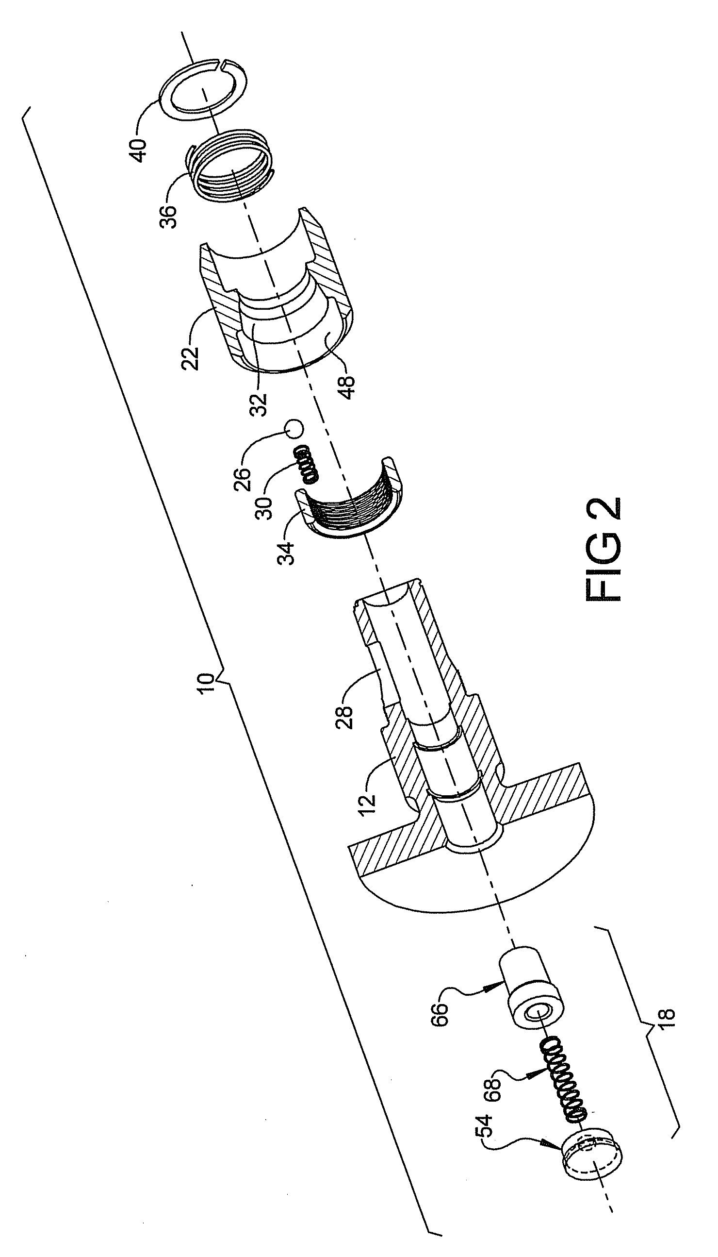
A bit retention device includes a shaft having a sidewall defining a hexagonal cavity extending from a first end thereof and a ball groove extending through the sidewall and communicating with the hexagonal cavity. A ball is disposed in the ball groove and a ball spring engages the ball and biases the ball toward the first end. An actuator sleeve surrounding the shaft includes an internal ramp engaging the ball. The internal ramp includes a shallow ramp portion having a first angle of inclination with respect to a center axis and a steep ramp portion having a second angle of inclination with respect to said center axis of said shaft that is greater than the first angle of inclination. A spring biased plunger assembly is disposed in the bore for biasing a bit received in the bore in a direction toward the insertion end.

Description

FIELD[0001]The present disclosure relates to power or hand tool bit retention devices, variously known as “auxiliary chucks,”“chucks,”“adapters,” or “bit holders” for removably receiving tool bits, such as fastener drivers, drill bits, or the like, for rotation therewith when the power tool is actuated or the hand tool is manually rotated. More particularly, the present disclosure relates to a bit retention device configured for rapid and easy insertion and removal of a bit.BACKGROUND AND SUMMARY[0002]This section provides background information related to the present disclosure which is not necessarily prior art.[0003]Bit retention devices for power and hand tools have become increasingly common, especially as the need and desirability of wider versatility and the use of power tools and hand tools has increased. Such bit retention devices allow the hand or power tool to be used with any of a number of interchangeable bits. This, in turn, has resulted in demands for greater speed, c...

Claims


Application Information

Patent Timeline
Patent Type & Authority Applications(United States)
IPC IPC(8): B23B31/107
CPCB23B31/1071B25B23/0035Y10T279/17196Y10T279/17752B25B23/0057
Inventor PUZIO, DANIELKUSMIERSKI, ROBERT G.TOROK, JEREMY
Owner BLACK & DECKER INC
Learn More