
Circuit for reducing standby leakage in a memory unit

a technology of memory units and circuits, applied in information storage, static storage, digital storage, etc., can solve the problems of not producing a very consistent low voltage supply and the inability to retain contents using that technique, and achieve the effect of reducing standby leakag

Inactive Publication Date: 2005-01-27
TEXAS INSTR INC
View PDF3 Cites 9 Cited by
  • Summary
  • Abstract
  • Description
  • Claims
  • Application Information

AI Technical Summary

Benefits of technology

[0009] According to one aspect of the present invention, a circuit for reducing standby leakage in a memory unit contains a capacitive divider coupled to the memory unit so as to generate a voltage across the memory unit, which is adequate to retain memory values during a sleep state and a standby state.
[0010] According to another aspect of the present invention, an inductive circuit for reducing standby leakage in a memory unit includes an inductive divider coupled to the memory unit so as to generate a voltage across the memory unit, which is adequate to retain memory values during a sleep state and a standby state.

Problems solved by technology

Some circuitry may be switched-off completely using series switches, but volatile memory devices, such as SRAM, that need to retain their contents cannot use that technique, since they lose their data if power is completely removed.
The problem encountered when doing this is that the reduced voltage across the SRAM cell has to be generated by a low drop-out (LDO) voltage supply, which requires operating current, and dissipated power equivalent to the leakage multiplied by the voltage between the supply voltage and standby voltage.
Alternatively, a passive series regulator can be used which dissipates dissipated power equivalent to the leakage multiplied by the voltage between the supply voltage and standby voltage, and may not produce a very consistent low voltage supply.

Method used


Image

  • Circuit for reducing standby leakage in a memory unit
  • Circuit for reducing standby leakage in a memory unit
  • Circuit for reducing standby leakage in a memory unit

Examples


implementation embodiment

[0021] Implementation Embodiment in Hardware

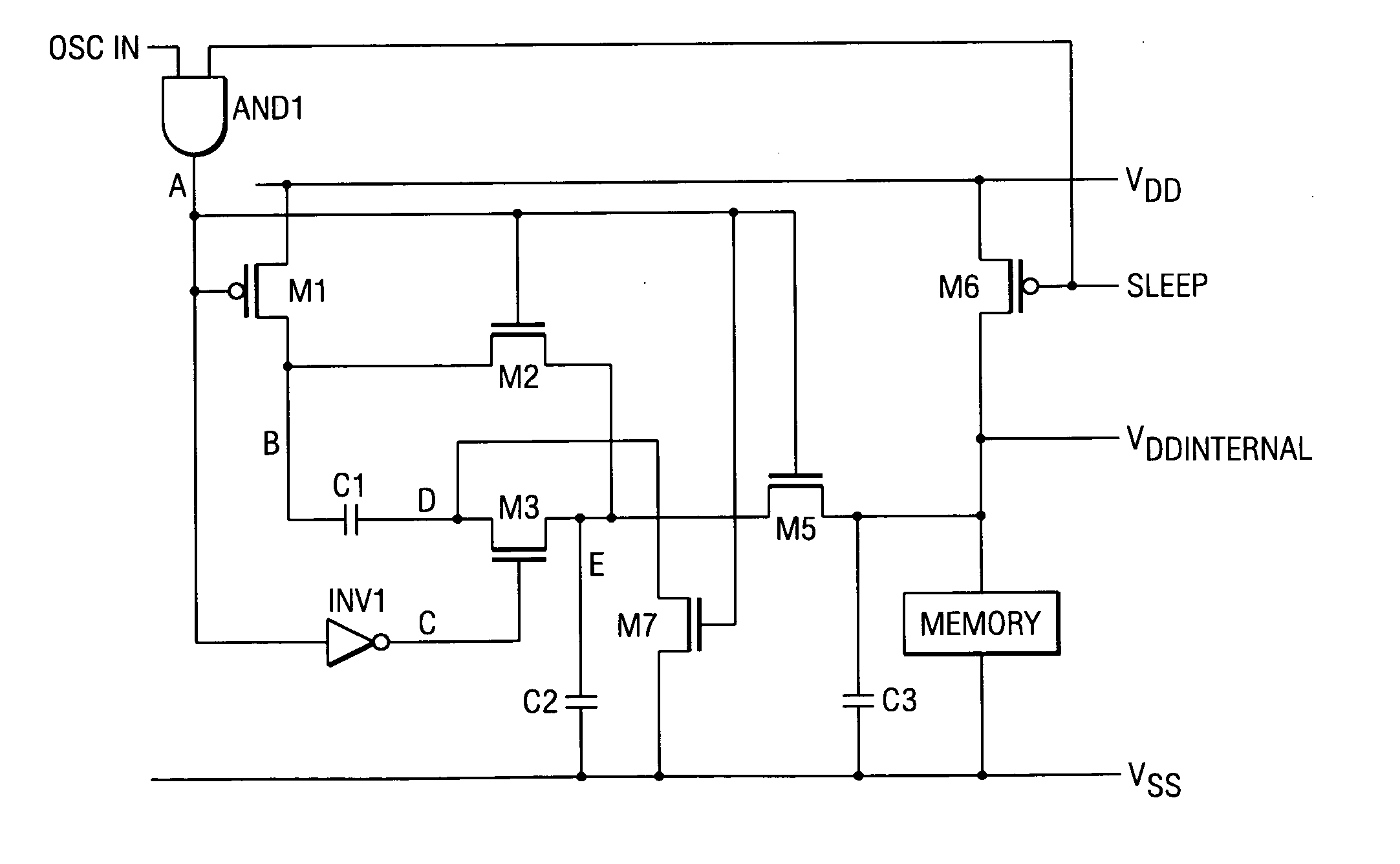
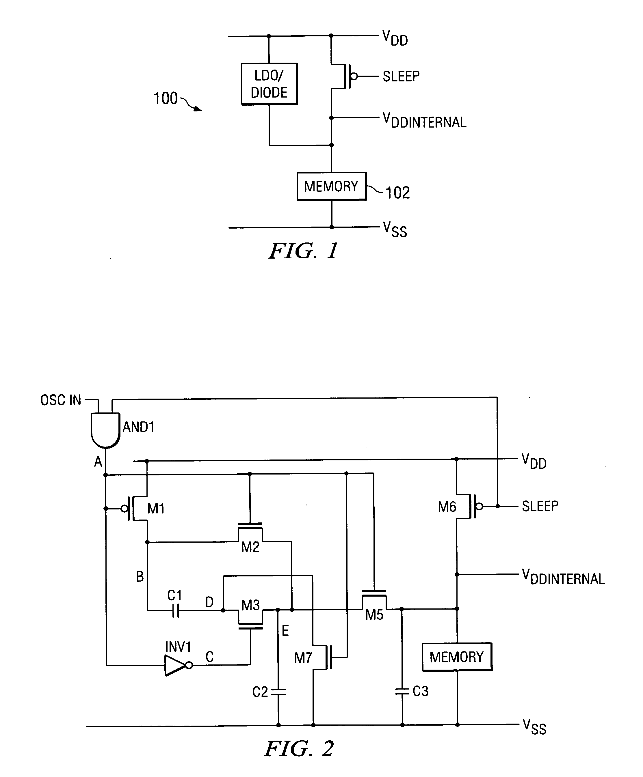
[0022]FIG. 2 is a schematic and block diagram of a circuit 200 having a memory unit 202 connected to a capacitive divider 204 in a low current standby state, according to one embodiment of the present invention. Accordingly, the memory unit 202 is not driven in the standby state by an LDO or a series regulator, but by a capacitor divider 204 that generates a division of Vdd such as Vdd / 2, Vdd / 3, Vdd / 4 and so on. In an embodiment, the capacitive divider 204 is coupled to the memory unit 202 through a non-illustrated substrate (on-chip).

[0023] It is assumed that the ‘osc in’ runs continuously as a square wave of approximately 1-100 MHz, although the oscillator may be off when not in the sleep or standby mode. In one embodiment, the capacitive divider 204 is configured for varying an oscillator frequency in accordance with the generated voltage so as to minimize switching losses.

[0024] Operational State

[0025] The ‘sleep’ input is LOW durin...


PUM


Abstract

A circuit for reducing standby leakage in a memory unit contains a capacitive divider coupled to the memory unit so as to generate a voltage across the memory unit, which is adequate to retain memory values during one of a sleep state and a standby state. An inductive circuit for reducing standby leakage in a memory unit includes an inductive divider coupled to the memory unit so as to generate a voltage across the memory unit, which is adequate to retain memory values during one of a sleep state and a standby state.

Description

FIELD OF THE INVENTION [0001] The present invention generally relates to the reduction of standby power in memory units and more particularly relates to reducing standby leakage in memory units such as a static random access memory (SRAM). BACKGROUND OF THE INVENTION [0002] Many electronic devices such as mobile phones and personal digital assistants (PDAs) are operated by battery power supplies and use SRAMs for data memory. [0003] Recently, it has become important to place circuitry into a deep-sleep mode to minimize circuit leakage. Some circuitry may be switched-off completely using series switches, but volatile memory devices, such as SRAM, that need to retain their contents cannot use that technique, since they lose their data if power is completely removed. [0004] Therefore, to reduce the leakage of memory devices during the standby state, it has been proposed to reduce the voltage across the memory cell, as shown in FIG. 1. The problem encountered when doing this is that the...

Claims


Application Information

Patent Timeline
IPC IPC(8): G11C5/14G11C11/413G11C11/417
CPCG11C11/413G11C5/147
Inventor MARSHALL, ANDREW
Owner TEXAS INSTR INC
Learn More