Resonant device with improved features

a technology of resonant devices and features, applied in the field of resonant devices, can solve the problems of insufficient performance of this type of oscillator, and achieve the effect of enhancing performance and being easy to implemen

Active Publication Date: 2010-09-02
COMMISSARIAT A LENERGIE ATOMIQUE ET AUX ENERGIES ALTERNATIVES
View PDF2 Cites 3 Cited by
  • Summary
  • Abstract
  • Description
  • Claims
  • Application Information

AI Technical Summary

Benefits of technology

[0005]The object of the invention consists in providing a resonant device that is easy

Problems solved by technology

The performances of this type of oscillator are however greatly insufficient, and a new archit

Method used


Image

  • Resonant device with improved features
  • Resonant device with improved features
  • Resonant device with improved features

Examples


Embodiment Construction

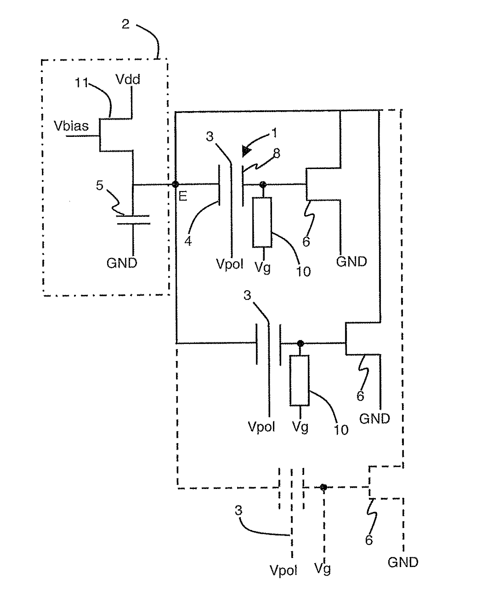
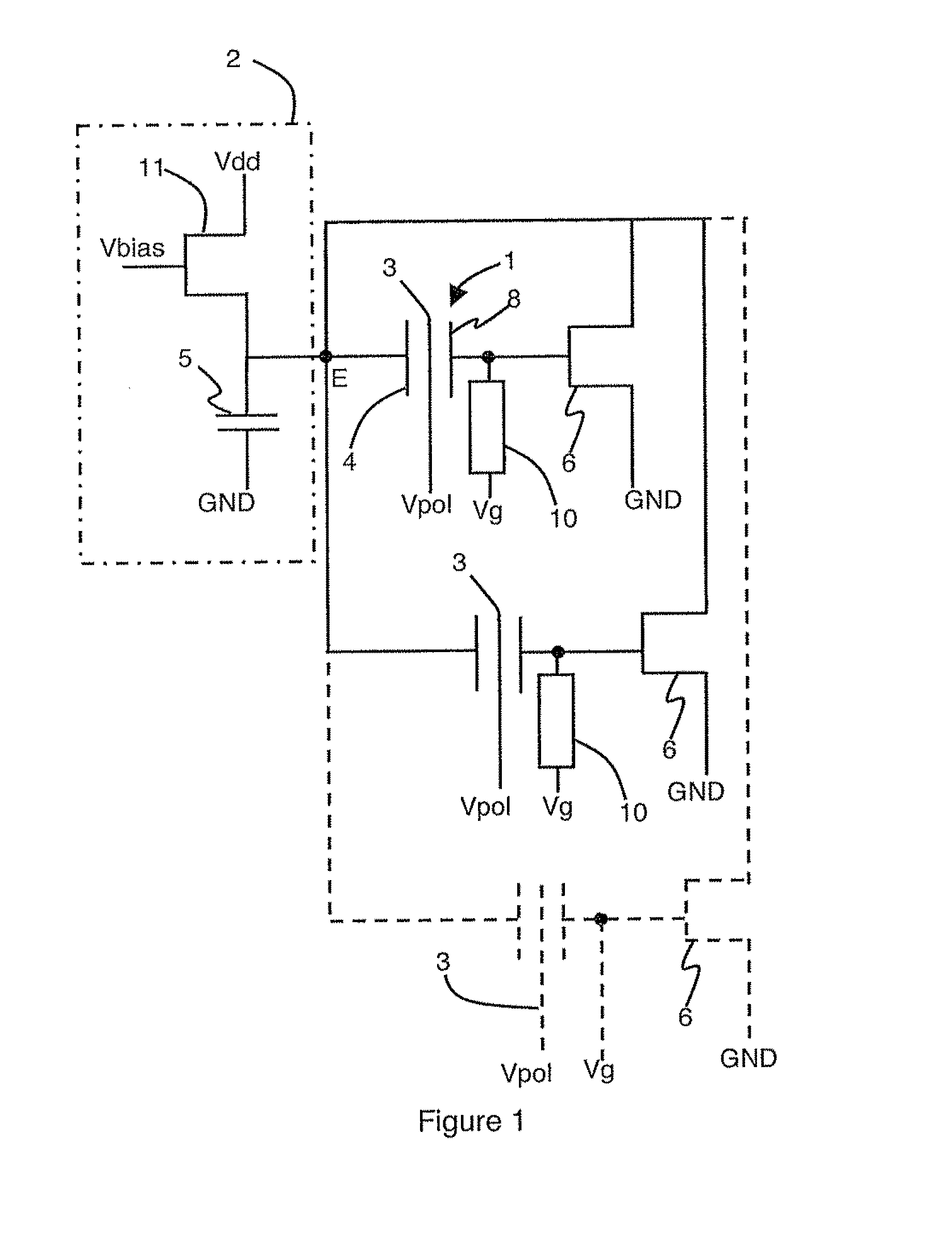
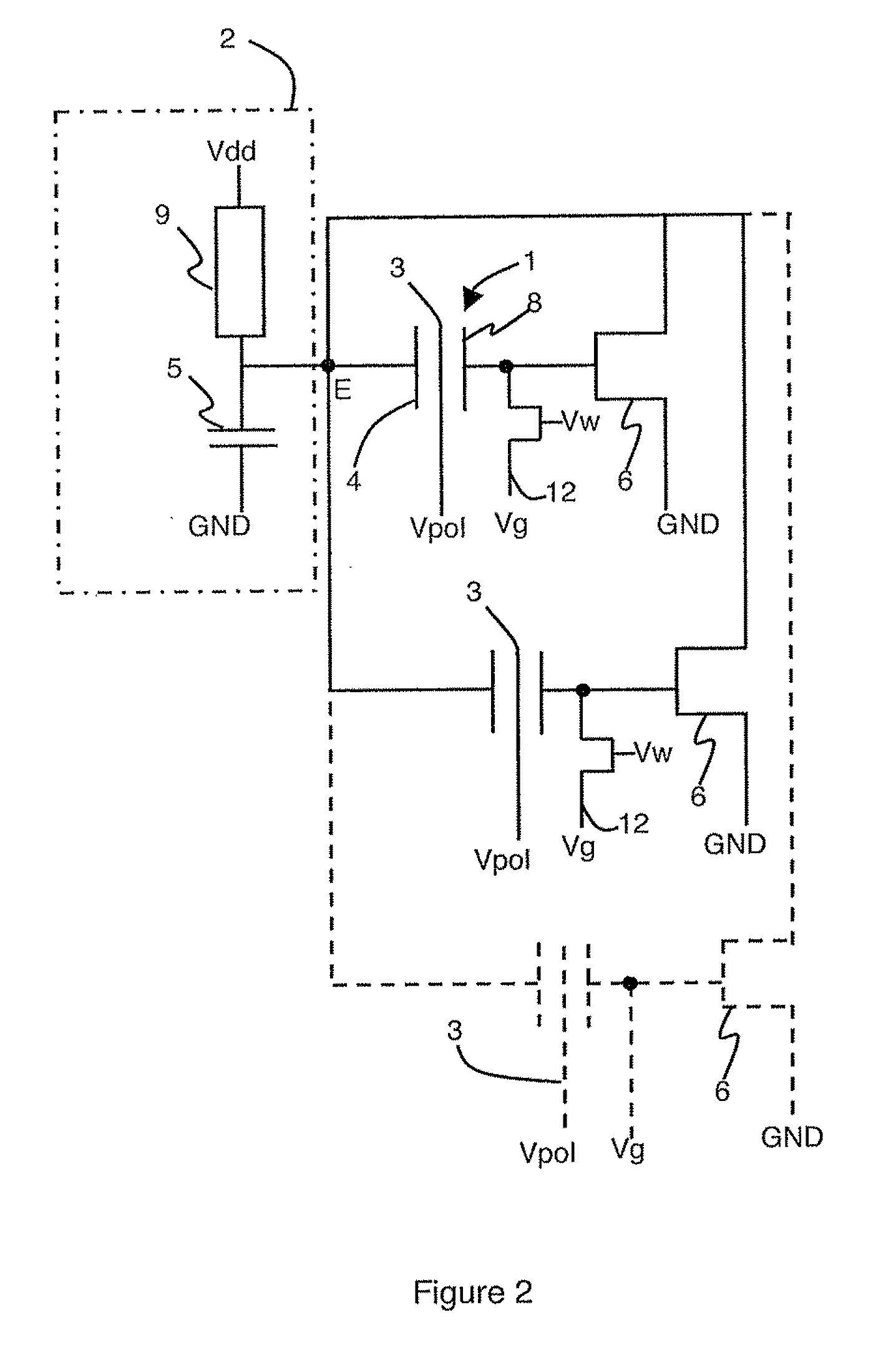
[0009]As illustrated in FIG. 1, the resonant device comprises a plurality of oscillators, at least two oscillators, that are synchronized. Each oscillator comprises a resonator 1 and its associated oscillation circuit which comprises a capacitive bias element 2. Bias element 2 is common to all the oscillators and comprises at least one capacitive load 5.

[0010]The oscillators forming the resonant device are simply electrically connected to one another. Each oscillator is dimensioned so as to present the same resonance frequency. The differences that exist between the resonance frequencies stem from the uncertainties in the production method, and these differences between the resonance frequencies can be compensated by adjusting the gain of their feedback loop. This adjustment of each gain is not a necessary condition but an advantageous embodiment.

[0011]Resonator 1 can for example be a quartz resonator, an electromechanical resonator advantageously of micrometric or nanometric size, ...


PUM


Abstract

The device resonant comprises a plurality of synchronized oscillators. Each oscillator comprises a resonator which comprises detection means providing detection signals representative of oscillation of the resonator to a feedback loop connected to an excitation input of the resonator. The detection signals control the conductivity of the feedback loop of the oscillator. The excitation inputs of all the resonators are connected to a common point which constitutes the output of the resonant device. A capacitive load is connected between said common point and a reference voltage.

Description

BACKGROUND OF THE INVENTION[0001]The invention relates to a resonant device.STATE OF THE ART[0002]In order to be able to continue the race towards miniaturization, micro-electronic circuits are having to integrate new functions while at the same time minimizing the surface area of the circuits. One of the major fields of study is integration of resonant devices within chips. Indeed, in a large number of fields such as gas-phase chemical sensors, molecular force sensors or mass spectrometers, it is of interest for the integrated circuit to comprise at least one oscillator. Designers are working on replacing the oscillator, which is an additional discrete component, by an integrated oscillator. By integrating this oscillator, it can then be hoped to obtain a gain in the energy consumed, in addition to the gain in surface area or in volume of the device, and an improvement of performances.[0003]Numerous publications deal with electromechanical resonators of micrometric or nanometric si...

Claims


Application Information

Patent Timeline
IPC IPC(8): H03L7/00H03B5/30
CPCH03B5/323
Inventor DURAFFOURG, LAURENTANDREUCCI, PHILIPPECOLINET, ERICHENTZ, SEBASTIENOLLIER, ERIC
Owner COMMISSARIAT A LENERGIE ATOMIQUE ET AUX ENERGIES ALTERNATIVES
Why Eureka
Try Eureka