
Method for verifications and fast QOS establishment

a verification method and verification method technology, applied in the field of communication network resources management, can solve the problems of high packet loss rate and long radio access delay, load level, and consequently, the delay is higher for office ieee 802.11 wlans

Inactive Publication Date: 2010-09-02
INTERTECH GLOBAL LLC
View PDF8 Cites 143 Cited by
  • Summary
  • Abstract
  • Description
  • Claims
  • Application Information

AI Technical Summary

Benefits of technology

[0025]It is yet another objective of the invention to provide methods for gradually adjusting initial allocations of QoS resources after a determined period of mobile wireless user terminals receiving communications services.

Problems solved by technology

Due to its contention-based CSMA / CA radio access technique, IEEE 802.11 WLANs are also characterized by high packet loss-rates and long radio access delays.
As a result, the load levels and consequently, delays are higher for office IEEE 802.11 WLANs.
Given its nascent state, cellular 3G networks are not as widely available as cellular GPRS networks.
So, if the user was using a streaming video application, there will be an abrupt disruption or degradation of video quality after the network switch.
It is during this period that mobile wireless user terminals and their applications are most vulnerable to disruption.
This is an intensive and time-consuming task for mobile terminal devices, which have limited battery power.
When a user switches frequently, mapping of QoS requirements becomes a processing overhead that adversely affects QoS performance.
Additionally, signaling required for negotiating QoS resources at new communications networks is also time-consuming because greater exchanges are required to confirm and establish appropriate QoS requirements, which are not known to the mobile terminal device.
Another problem arising from switching between technologies of different communications networks is that QoS resources are not efficiently allocated due to differences in mobility conditions.
So allocating identical QoS resources to both requests is inefficient as the first user from the cellular 3G will not completely utilize them.
This problem is exacerbated when there are large numbers of users moving to an IEEE 802.11 WLAN from different types of previous communications networks.
Related to the problem of inefficient resource allocation, is the problem of inaccurate QoS resource requests.
Based on extant technologies and prior arts, it is not possible for a communications network to verify the exact nature of a user's QoS resource request.
For example, when a user switches from a first to a second communications network, it is not possible to verify which type of network the user switched from, the level of resource utilization at the first network and the time duration spent at the first network.
As a result, the second communications network cannot allocate the optimal level of QoS resources.
So inaccurate resource requests, whether legitimate or illegitimate, cannot be verified by technologies of existing communications networks.
Such problems of abrupt performance changes, switching overhead, inefficient QoS resource allocations and unauthentcated QoS requests deprives mobile wireless user terminals of seamless communications.
Consequently, mobile wireless user terminals suffer from poor QoS performance.
The method, despite its theoretical basis, has limited practical appeal because it requires the two different networks to be in communications with each other.
So the proposed method is not effective in solving the needs of mobile wireless user terminals.
This method is disadvantaged similarly to [Prior-Art 1] in that it requires the two networks to be communicably coupled in order to be effective.
So in practice, this method is not a feasible solution to address the problems faced by mobile wireless user terminals that switch between different communications networks.
This is not feasible for the practical cases in which mobile wireless user terminals switch between distinct communications networks that do not offer a medium for coordination.
The foreign agents of this method are not effective in addressing the problems highlighted earlier.
In particular, these users are faced with the problems of abrupt performance changes, switching overhead, inefficient QoS resource allocations and unauthenticated QoS requests, which consequently deprive them of seamless communications.

Method used


Image

  • Method for verifications and fast QOS establishment
  • Method for verifications and fast QOS establishment
  • Method for verifications and fast QOS establishment

Examples


embodiment 1

Distributing verified QoS History

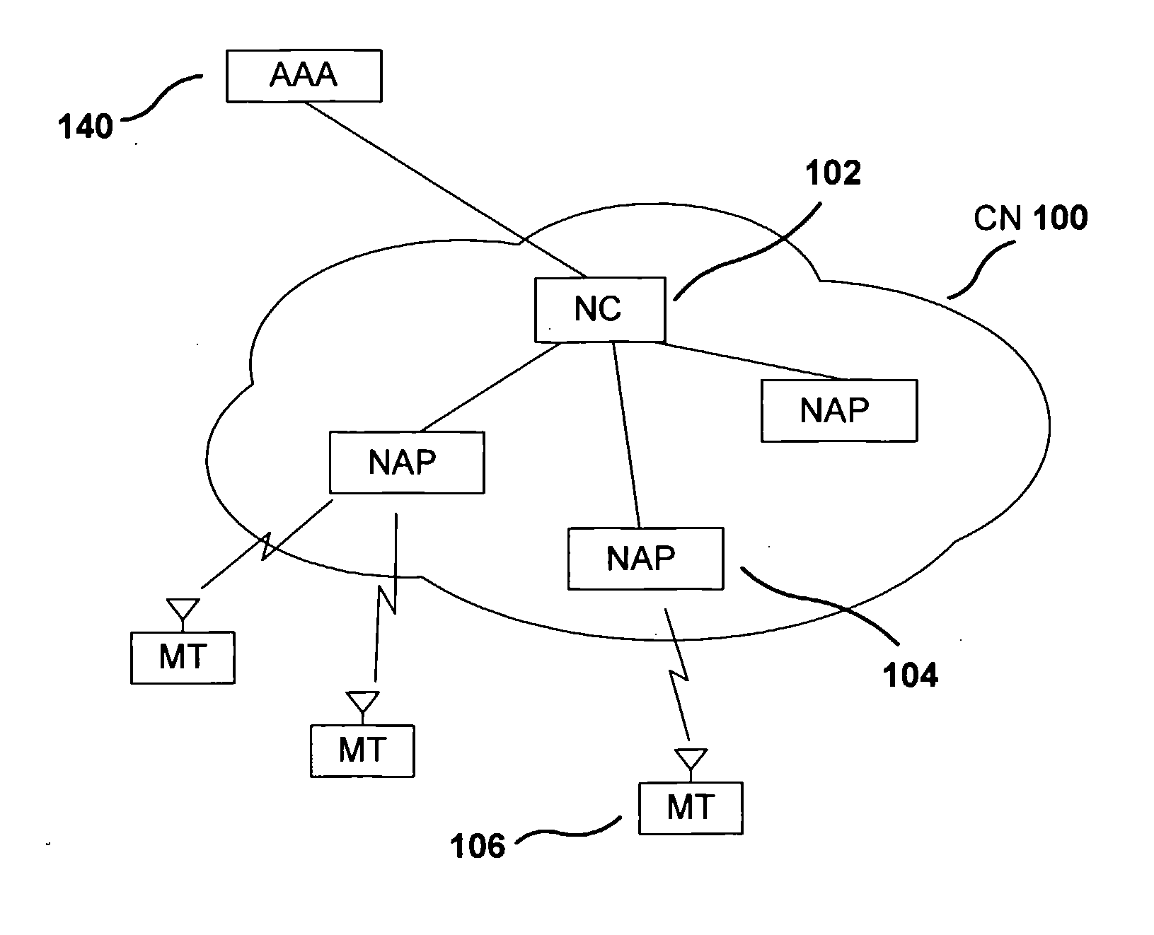
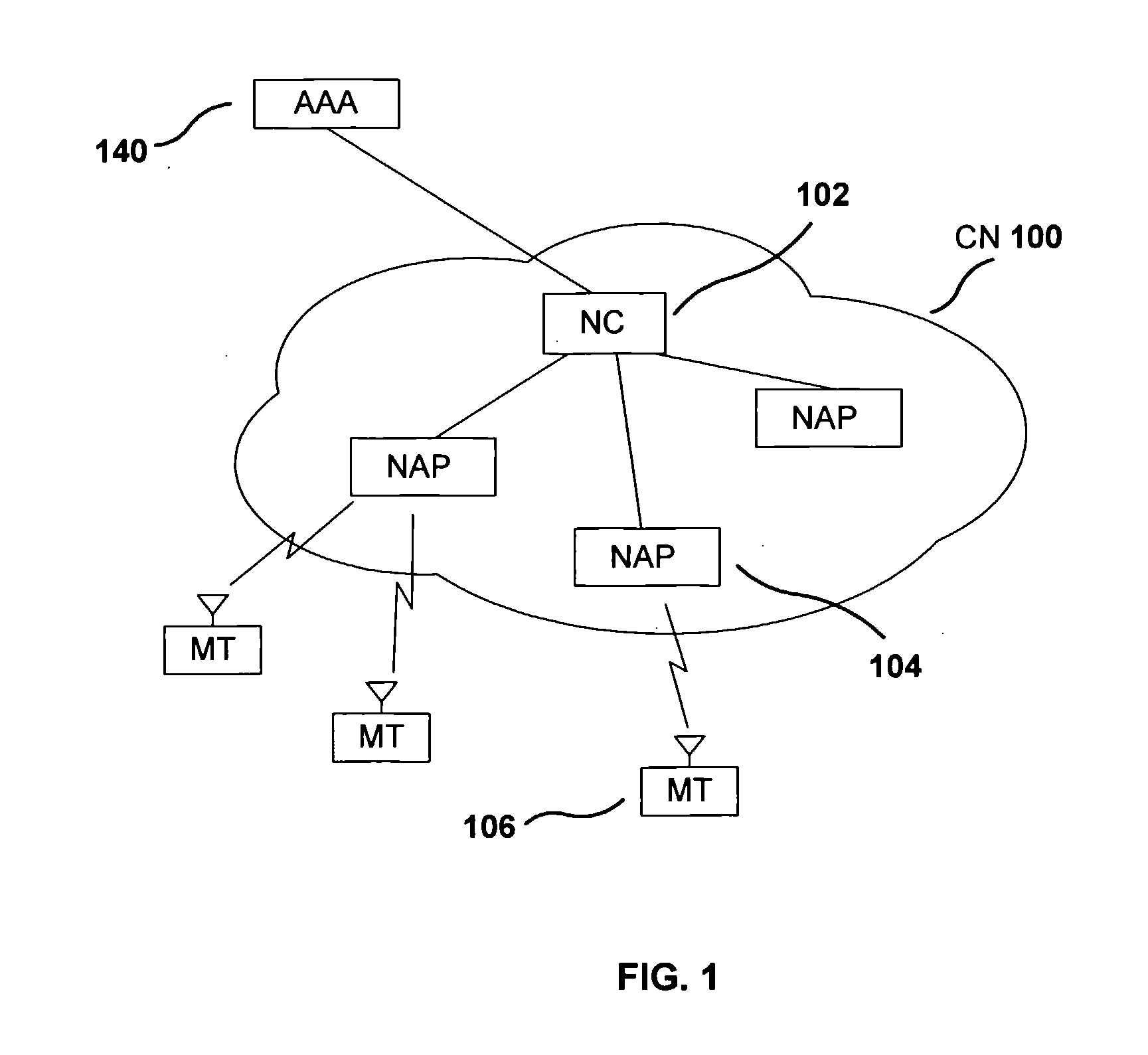
[0054]With reference to FIG. 1, a communications network (CN) (100) provides services to a single or plurality of mobile terminals (MT), such as MT (106). CN (100) comprises network controller (NC) (102) and a single or plurality of network attachment points (NAP) such as NAP (104). CN (100) may be interfaced to a single or plurality of other communications network such as Internet.

[0055]NC (102) is representative of a controller entity capable of coordinating network resources, provisioning NAPs, such as NAP (104), and controlling MTs, such as MT (106). NAP (104) is representative of a contact entity capable of establishing and maintaining radio interfaces with MTs, such as MT (106), monitoring radio activity and relaying communications traffic between MTs and CNs. NC (102) and NAP (104) are communicably coupled by means of wireline or wireless links.

[0056]NC (102) and NAP (104) assume different roles for different communications networks. For IEEE ...

embodiment 2

Sequence QoS History Info Unit

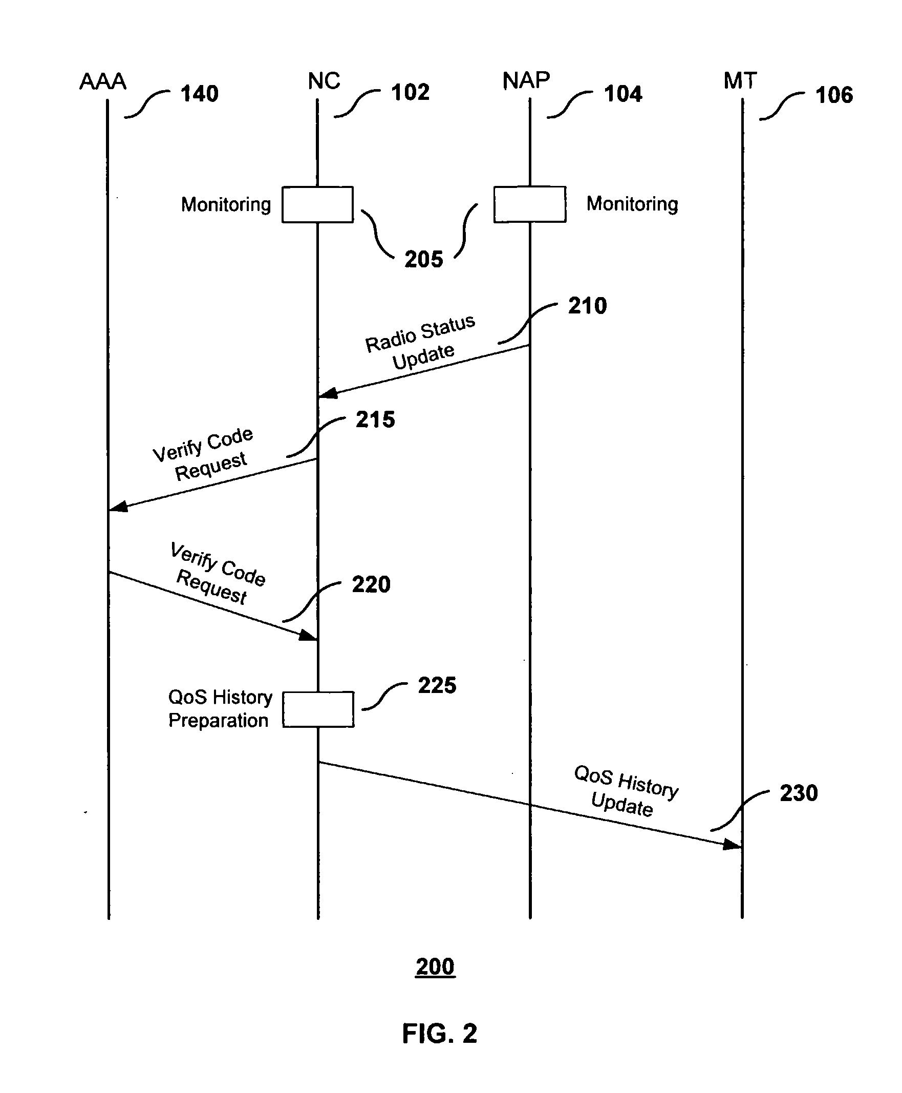
[0065]The sequence of operations among NC (102), NAP (104), AAA (140) and MT (106) is described hereinafter with aid of FIG. 2. Additionally, FIG. 14 is used to illustrate the structure (1400) of messages exchanged in the current invention. Each message begins with a 1-byte Type field (1405) with a value corresponding to the nature of the message. Subsequent descriptions of messages include their Type (1405) values. The C field (1410) is denotes if the message is destined for a network controller or originated from a network controller. A ‘0’ value denotes a message from a NC and a ‘1’ value denotes a message to a NC. The subsequent Length field (1415) denotes the total length of the message in bytes. Subsequent Message Element fields (1420) comprise various parameters and settings for the message type.

[0066]In the operational sequence (200), NAP (104) and NC (102) regularly monitor radio link performance metrics and communications performance metrics, ...

embodiment 3

Fast Re-Establishment

[0071]In one embodiment, the QoS history information unit is used to reduce signaling and processing operations during transitions between heterogeneous communications networks and enhance seamless communications. As described above, the transition period between communications networks is critical and must ensure that mobile wireless user terminals receive communications services that are as seamless as possible. It is for this reason that in the present embodiment, the initial signaling required between a mobile terminal and new communications network are bypassed by means of sending the QoS history information unit. The new communications network verifies the information unit and establishes the necessary resources and state information without requiring time-consuming signaling operations.

[0072]FIG. 3 is used to illustrate the operations of the present embodiment. Here, MT (106) is initially associated with CN (100) and receives corresponding communications ...


PUM


Abstract

A wireless communication system is provided for rapidly establishing the QoS resource on different communication networks. In this system, the NAP (104) evaluates a network resource used by the MT (106), and generates the QoS history information unit indicating the evaluation result. The AAA (140) authenticates the QoS history information unit generated by the NAP (104). The NAP (104) transmits the authenticated QoS history information unit to the MT (106). The MT (106) request for a resource establishment to the NAP (304) when switching the communicating party from the NAP (104) to the NAP (304), and transmits the QoS history information unit. The NAP (304) verifies the authenticity of the QoS history information unit to the AAA (140) when receiving the request for resource establishment from the MT (106) and allocates the network resource to the MT (106) based on the QoS history information unit.

Description

TECHNICAL FIELD[0001]The present invention pertains to resource management in communications networks and, more particularly, it relates to the verification and establishment of quality of service resources in mobile environments.BACKGROUND ART[0002][Prior-Art 1] U.S. Pat. No. 6,693,912B1, “Network Interconnectivity Apparatus and Active Quality of Service Mapping Method,” February 2004.[0003][Prior-Art 2] US 2004 / 000 1511 A1, “Catprobe,” June 2002.[0004][Prior-Art 3] US 2004 / 009 5912 A1, “Handover Resource Optimization,” November 2002.[0005]The increasing popularity of mobile wireless communications has resulted in the development of numerous communications technologies. Each technology addresses user needs in different environments, under different circumstances or during different time periods. Consequently, the entirety of user needs is addressed by a combination of different technologies. So users will utilize heterogeneous communications networks to satisfy their needs.[0006]Am...

Claims


Application Information

Patent Timeline
IPC IPC(8): H04W72/04H04W28/18H04W36/12H04W36/14H04W72/08
CPCH04L47/10H04L47/14H04L47/24H04W28/18H04L63/123H04W12/10H04L47/2491H04W12/61H04W8/04
Inventor GOVINDAN, SARAVANANCHENG, HONGTAN, PEK YEW
Owner INTERTECH GLOBAL LLC
Learn More