Cutting tool and cutting insert

Inactive Publication Date: 2010-09-02
MITSUBISHI MATERIALS CORP
View PDF10 Cites 36 Cited by
  • Summary
  • Abstract
  • Description
  • Claims
  • Application Information

AI Technical Summary

Benefits of technology

[0030]According to the present invention, it is possible to provide; a cutting tool that can use in sequence main cutting edges and sub-cutting edges formed on each of the sides of the heptagonal faces and also perform stable cutting consistently, even with a negative type approximately heptagonal planar cutting insert where both sides can be used and wherein sub-cutting edges are provided at the corners, and a cutting insert mounted removably on the cutting tool.

Problems solved by technology

However, in the planar octagonal shape as above, since the angle formed by adjacent cutting edges is 135°, which is large, then in the case where the corner angle (angle formed with the axis) of the main cutting edge directed toward the tip (forward in the cutting direction) of the tool body and in the radial-outer direction is set for example to 45° or greater, there is concern that the side face adjacent to the side face where the main cutting edge is formed and toward the rear (backward in the cutting direction) of the tool body, interferes with the workpiece.
On the other hand, if the corner angle is set to less than 45° in order to relieve the side face from the workpiece, the side face adjacent to the side face where the main cutting edge is formed and forward in the cutting direction, interferes with the workpiece.
Furthermore, in the case where the number of cutting edges (number of sides) is increased in this manner, if the size of the cutting insert is fixed, the length of each of the cutting edges is shortened, and hence the amount of cut is reduced, which makes it unable to perform cutting efficiently.

Method used


Image

  • Cutting tool and cutting insert
  • Cutting tool and cutting insert
  • Cutting tool and cutting insert

Examples


Embodiment Construction

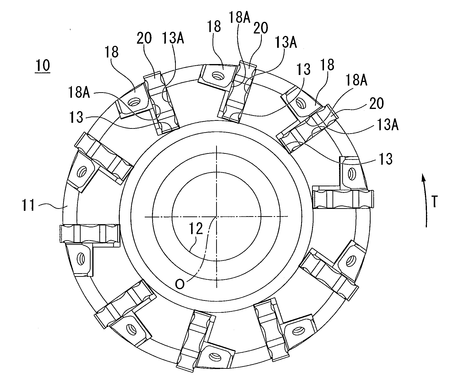
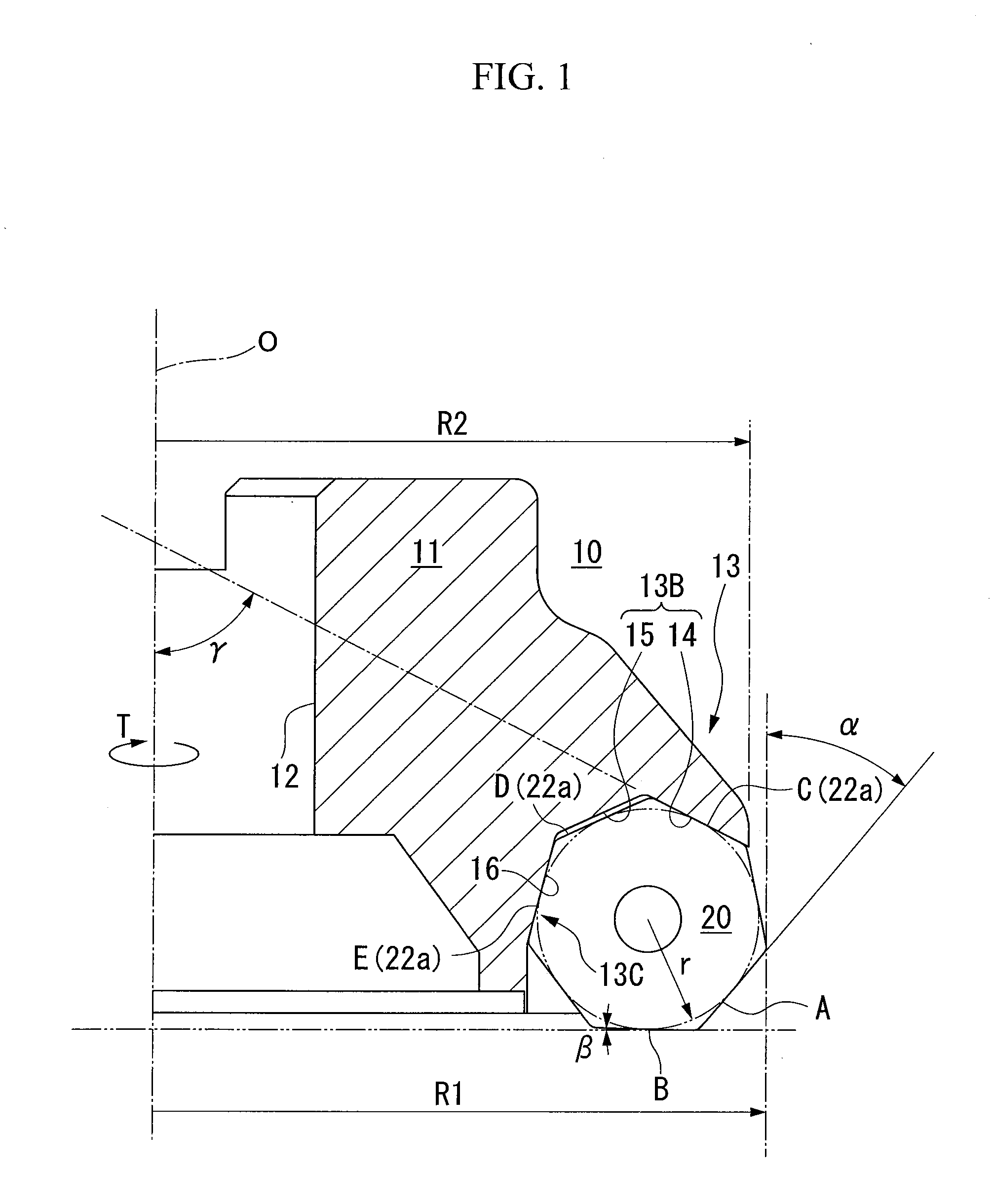
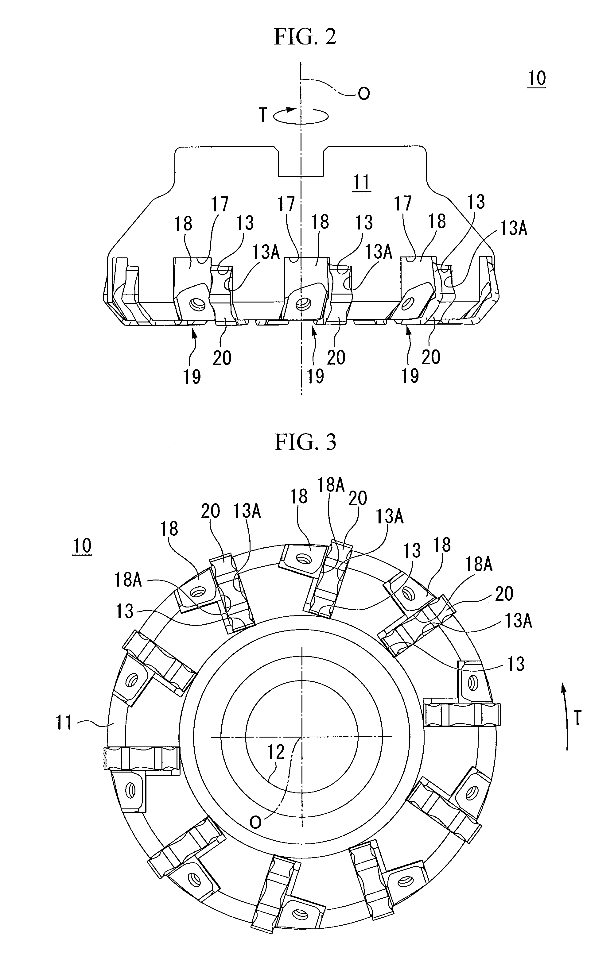
[0055]An embodiment of the present invention is described with reference to the appended drawings. FIG. 1 to FIG. 3 show a milling cutter, which is a cutting tool of the present embodiment. Furthermore, FIG. 4 to FIG. 7 show a cutting insert to be mounted on the milling cutter. The milling cutter of the present embodiment is so-called right handed, which rotates right-handedly (direction T in FIG. 1) when viewed facing the finished surface, and a right handed cutting insert is mounted thereon.

[0056]The milling cutter 10 is used when surface machining is performed on a workpiece such as cast iron, steel or the like, and has a tool body of a substantially disk shape with an axis O in the center as shown in FIG. 2 and FIG. 3. A mounting hole 12 is formed in the tool body 11 extending along the axis O.

[0057]Mounting seats 13 on which cutting inserts 20 described later are mounted, are formed in the outer periphery at the tip of the tool body 11, such that they open at the tip (forward i...


PUM

PropertyMeasurementUnit
Angleaaaaaaaaaa

Abstract

A cutting tool is provided with a tool body which rotates about an axis thereof, and a cutting insert mounted removably on the outer periphery at the tip of the tool body, wherein: the cutting insert has a front / back-reversal symmetric substantially regular heptagonal plane shape having two heptagonal faces parallel with each other, a side face continuous with each of the heptagonal faces at right angles, and a cutting edge provided on each ridge line between the heptagonal face and the side face; the cutting edge includes a main cutting edge projected onto the side of the regular heptagon, and sub-cutting edges that extend from opposite ends of the main cutting edge so as to incline toward the center of the heptagonal face and connect the adjacent main cutting edges, and the tool body is equipped with a mounting seat that retains the cutting insert such that one of the main cutting edge is directed toward the tip side of the tool body and in a radial-outer direction in order to make it to work in cutting, and a corner angle α between one of the main cutting edges and the axis satisfy a relation 40°≦α≦44°.

Description

CROSS-REFERENCE TO PRIOR APPLICATION[0001]This is the U.S. National Phase Application under 35 U.S.C. §371 of International Patent Application No. PCT / JP2007 / 061345 filed Jun. 5, 2007, which claims the benefit of Japanese Patent Application No. 2006-157050 filed Jun. 6, 2006, both of which are incorporated by reference herein. The International Application was published in Japanese on Dec. 13, 2007 as WO2007 / 142224 A1 under PCT Article 21(2).TECHNICAL FIELD[0002]The present invention relates to a cutting tool used when surface machining is applied to a workpiece, and a cutting insert that is mounted removably on the cutting tool.BACKGROUND ART[0003]Heretofore, as a cutting tool used when cutting is applied to a workpiece, there is known for example as described in Patent Document 1, a cutting tool on which inserts incorporating cutting edges are mounted removably on the outer periphery at the tip of a tool body.[0004]The cutting tool disclosed in Patent Document 1 is rotated at high...

Claims


Application Information

Patent Timeline
IPC IPC(8): B23C5/20B23B27/16B23B27/22
CPCB23C5/06B23C5/207B23C2200/125B23C2200/201B23C2200/206Y10T407/1924B23C2210/0407B23C2210/206Y10T407/23Y10T407/235B23C2200/366B23C2200/0488B23C2200/208B23C2200/205B23C5/202B23C5/20B23B27/16B23B27/14
Inventor TAKAHASHI, HIDEBUMINARITA, TOURU
Owner MITSUBISHI MATERIALS CORP
Why Eureka
Try Eureka