
Method for producing a component with a relief surface and a component of this type

a technology of relief surface and component, which is applied in the direction of manufacturing tools, instruments, transportation and packaging, etc., can solve the problems of complex operation and unsuitability, and achieve the effect of thinning the area

Inactive Publication Date: 2010-09-02
INTERGLARION LTD (AT)
View PDF4 Cites 41 Cited by
  • Summary
  • Abstract
  • Description
  • Claims
  • Application Information

AI Technical Summary

Benefits of technology

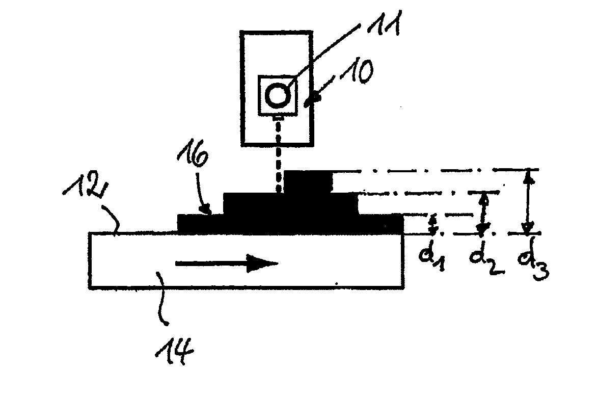
[0013]Even relatively thick or high regions of a surface can easily be produced by applying further relief liquid onto thinner relief surface areas already provided with relief liquid, in that the curable relief liquid is applied in several layers one on top of the other according to the relief data. For example, intensively highlighted parts of an original or intensively colored parts of an original can be embodied with much greater thickness compared to the other regions of the original.

Problems solved by technology

These known methods on the one hand are complex to carry out and on the other hand they are not suitable for imitating the large variety of natural three-dimensional surfaces that are not repeated in the intervals of a circumference of a calender roll.

Method used


Image

  • Method for producing a component with a relief surface and a component of this type
  • Method for producing a component with a relief surface and a component of this type
  • Method for producing a component with a relief surface and a component of this type

Examples


Embodiment Construction

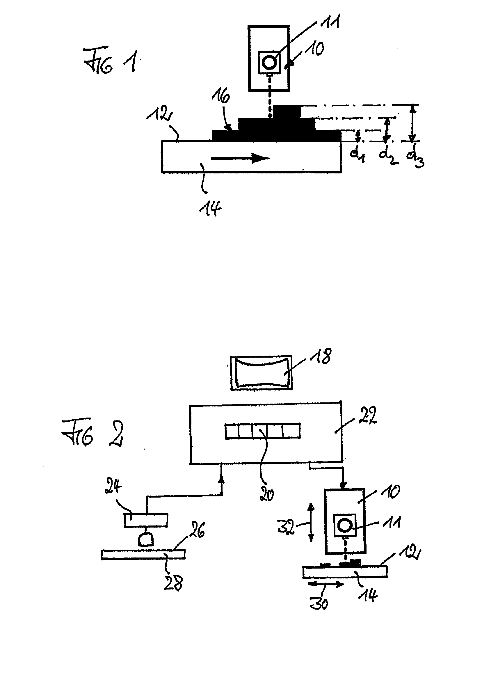
[0031]FIG. 1 shows diagrammatically an inkjet printing device 10 for inkjet printing of a surface 12 of an unfinished component 14.

[0032]The inkjet printing device is a design known per se. Droplets of coloring liquid are thereby sprayed from spray nozzles so that with precise control of a relative motion between the print head 11 provided with the nozzles and the component to be printed and by controlling the number of liquid droplets emitted by the individual spray nozzles or also the volume of the droplets of liquid, predetermined surface locations of the surface to be printed can be provided with predetermined quantities of coloring liquid. For color printing, for example, color-specific nozzles can be provided, which are loaded with coloring liquids of predetermined colors such that different colors are produced with an intensity depending on the absolute quantities of the coloring liquids on the surface depending on the relative quantity of the coloring liquids sprayed onto a ...


PUM

PropertyMeasurementUnit
areasaaaaaaaaaa
heightaaaaaaaaaa
three-dimensional structureaaaaaaaaaa

Abstract

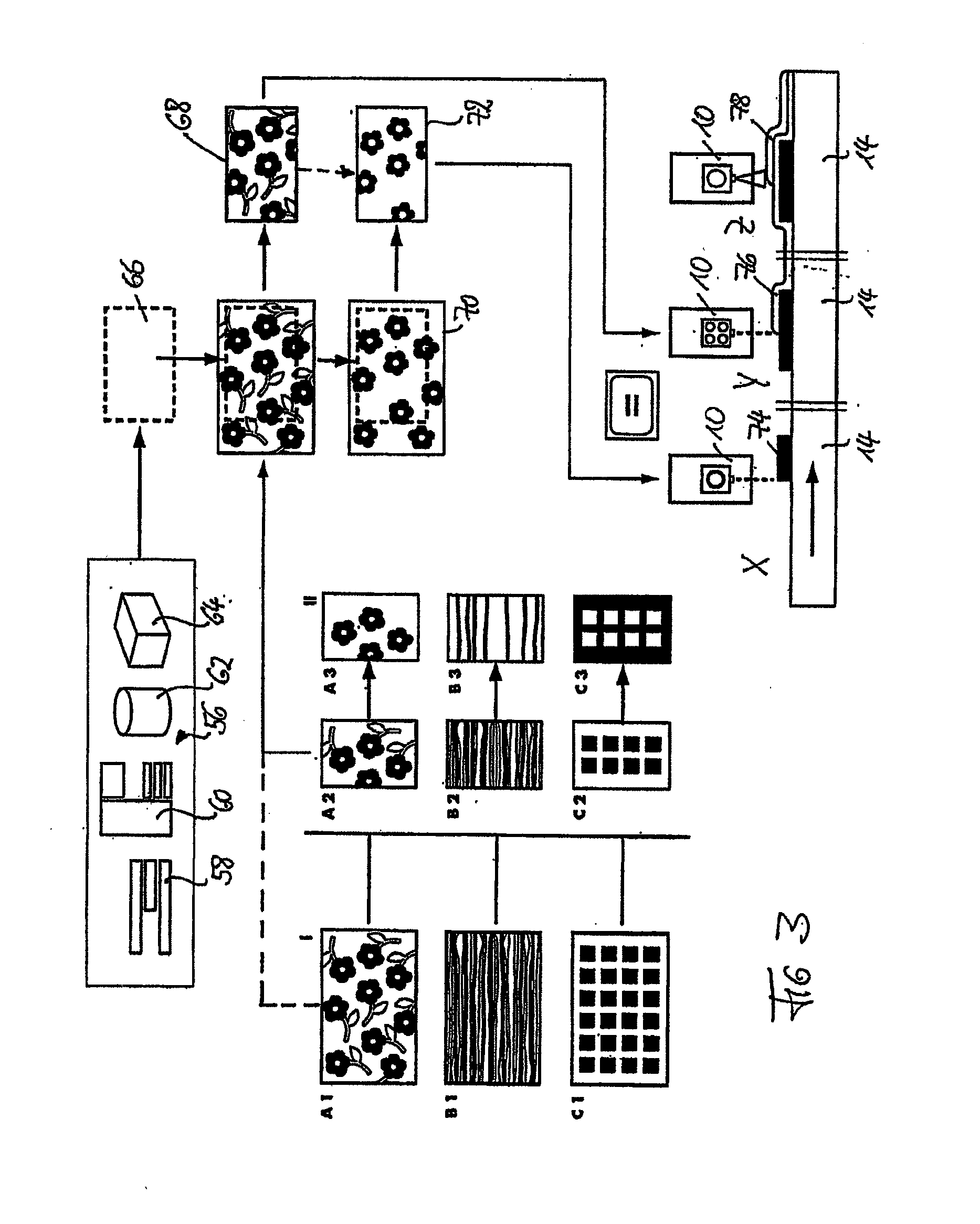
In a method for producing a component with a relief surface, the relief surface is produced by printing an unfinished component (14) with a curable relief liquid by means of a digital printing method controlled by electronic data processing, wherein the electronically stored design (72) corresponding to the relief surface contains relief data assigned to two-dimensional surface elements of the relief design, which relief data correspond to the quantity of the relief liquid to be applied for each surface element.

Description

CROSS-REFERENCE TO RELATED APPLICATIONS[0001]The present application is a U.S. National Stage of International Patent Application No. PCT / EP2008 / 003673 filed May 7, 2008, and claims priority under 35 U.S.C. §§119 and 365 of German Patent Application No. 10 2007 022 919.6 filed May 14, 2007. Moreover, the disclosure of International Patent Application No. PCT / EP2008 / 003673 is expressly incorporated by reference herein in its entirety.BACKGROUND OF THE INVENTION[0002]1. Field of the Invention[0003]The invention relates to a method for producing a component with a relief surface and a component with a relief surface.[0004]2. Discussion of Background Information[0005]The task of producing components with relief surfaces arises for a variety of applications. For example, it is advantageous for the production of components, the surface of which has the appearance of a real wood surface, to give the surface a three-dimensional structure that imitates the real wood structure embodied with g...

Claims


Application Information

Patent Timeline
Patent Type & Authority Applications(United States)
IPC IPC(8): B41J2/01B32B3/10
CPCY10T428/24802B29C67/0059B29C64/112B41J2203/01
Inventor BAUER, JOERG R.
Owner INTERGLARION LTD (AT)
Learn More