Posterior Fixation System

a technology of fixation system and anterior cruciate ligament, which is applied in the field of orthopaedic implants, can solve the problems of long duration of surgery, impracticality of precision required to use such a rigid device, and potential complications such as pain and/or extended rehabilitation

Inactive Publication Date: 2010-09-02
WARSAW ORTHOPEDIC INC
View PDF82 Cites 135 Cited by
  • Summary
  • Abstract
  • Description
  • Claims
  • Application Information

AI Technical Summary

Problems solved by technology

While useful in certain circumstances, in many therapeutic situations the degree of precision required to use such an inflexible device is impractical, or can lead to a longer duration of surgery, potentially awkward angles for the surgeon and for the patient, with the potential for attendant complications such as pain and / or extended rehabilitation.

Method used


Image

  • Posterior Fixation System
  • Posterior Fixation System
  • Posterior Fixation System

Examples


Embodiment Construction

[0073]For the purpose of promoting an understanding of the principles of the invention, reference will now be made to the embodiments illustrated in the drawings and specific language will be used to describe the same. It will nevertheless be understood that no limitation of the scope of the invention is thereby intended, such alterations and further modifications in the illustrated device, and such further applications of the principles of the invention as illustrated therein, being contemplated as would normally occur to one skilled in the art to which the invention relates.

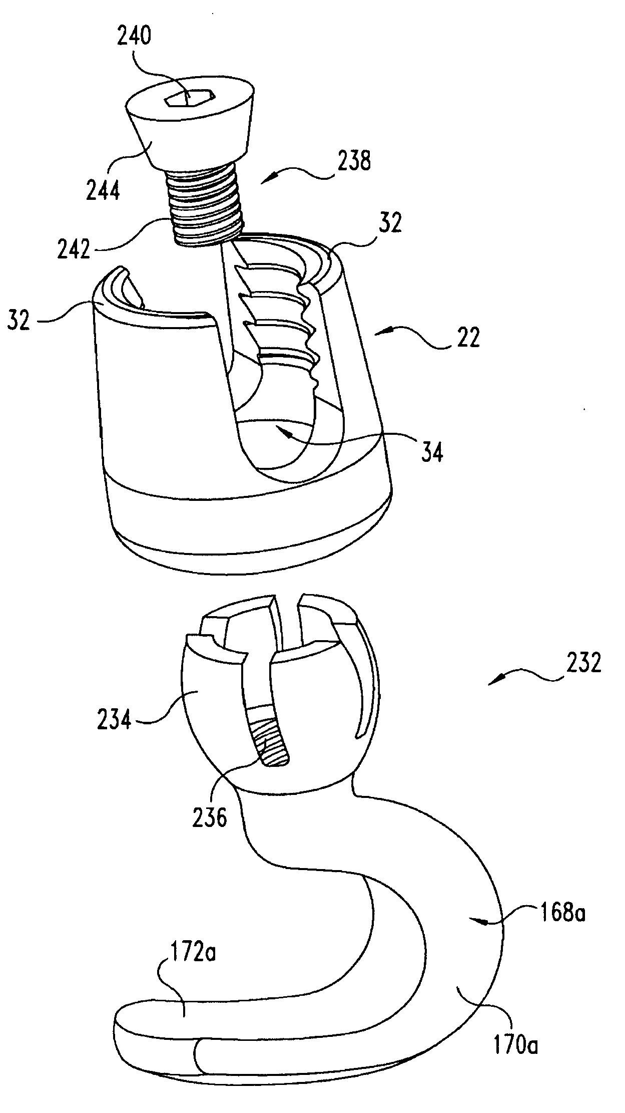
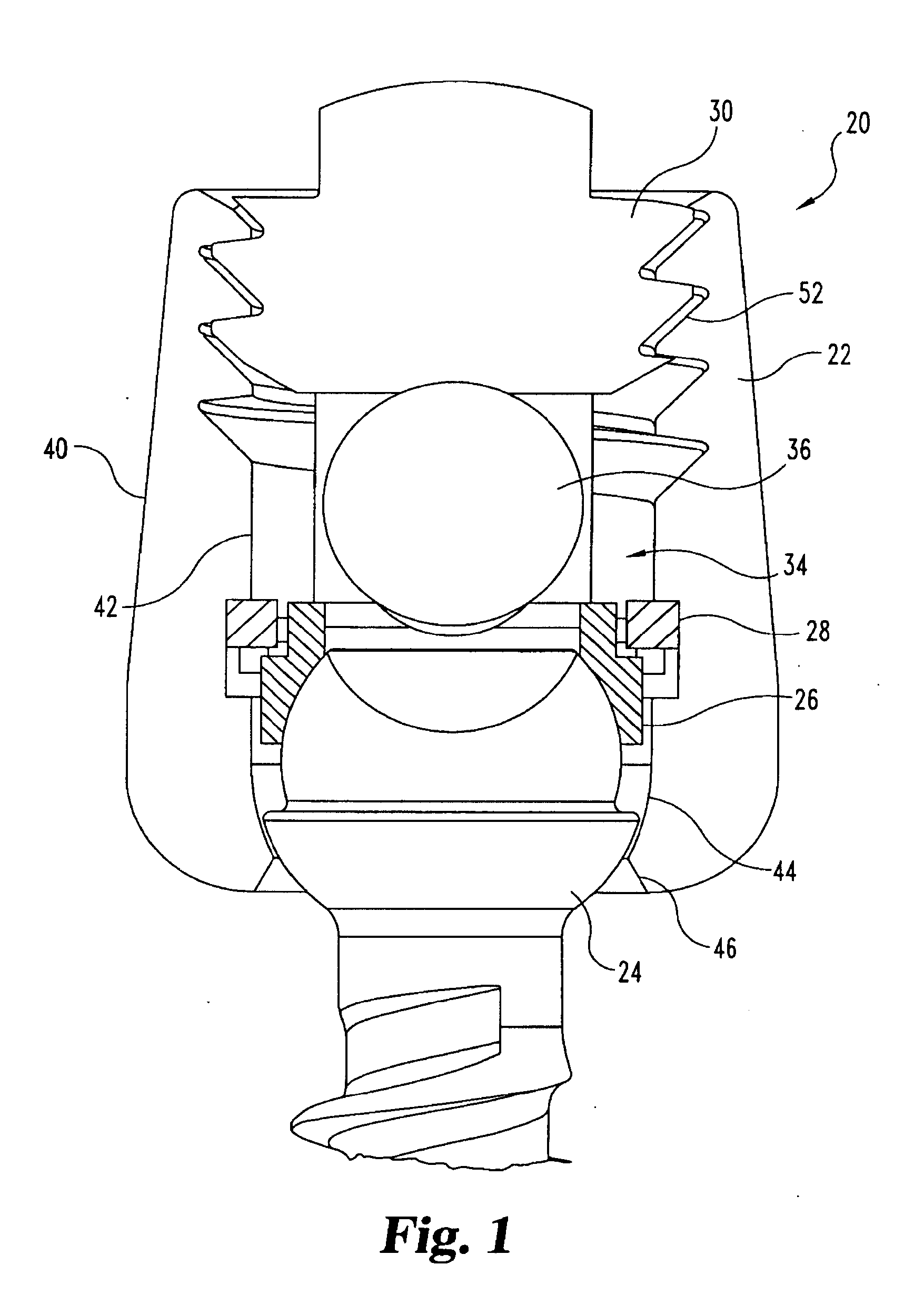
[0074]In FIG. 1, there is shown an embodiment of a multi-axial bone anchor assembly 20 according to the present invention. Bone anchor assembly 20 includes a saddle member 22, a bone anchoring member 24, and a washer (crown member) 26. In some embodiments, assembly 20 will further include a C-shaped snap ring 28 and a set screw 30, which are fitted with saddle member 22 as will be described hereafter.

[0075]As s...


PUM


Abstract

A posterior fixation system includes a saddle member, an anchoring member, an occipital plate, an occipital rod, and a cross-link connector. The anchoring member anchors the saddle member to bone. The saddle member includes a pair of upright portions that define a channel. The channel is adapted to receive an orthopedic rod, and the saddle member can include a hole to receive the anchoring member. The saddle member and the anchoring member can be coupled so as to allow multi-axial movement of the members. The anchoring member in one embodiment is a screw coupled to the hole of the saddle, and in another embodiment, the anchoring member is a hook. The offset member may be coupled to the saddle member to allow for offset connection of rods. Connection of individual rods can be accomplished by connecting the rods with the cross-link connector. The cross-link connector has an integrally formed cylindrical member that couples a pair of coupling portions together. The cylindrical member can be bent along multiple axes. The occipital plate secures the rods to the occipital bone of the skull. The occipital plate has a cross-shaped plate with a plurality of apertures defined in the plate and at least one saddle member coupled to the plate. Alternatively, the occipital rod can be secured to the occipital bone.

Description

BACKGROUND OF THE INVENTION[0001]The present invention generally relates to orthopedic implants used for correction of spinal injuries or deformities, and more specifically, but not exclusively, concerns apparatuses for fixing a portion of the spine, such as the cervical spine, to allow correction or healing thereof.[0002]In the realm of orthopedic surgery, it is well known to use implants to fix the position of bones. In this way, the healing of a broken bone can be promoted, and malformations or other injuries can be corrected. For example, in the field of spinal surgery, it is well known to place such implants into vertebrae for a number of reasons, including (a) correcting an abnormal curvature of the spine, including a scoliotic curvature, (b) to maintain appropriate spacing and provide support to broken or otherwise injured vertebrae, and (c) perform other therapies on the spinal column.[0003]Typical implant systems include several pieces, which commonly are useful and may be ...

Claims


Application Information

Patent Timeline
Patent Type & Authority Applications(United States)
IPC IPC(8): A61B17/70
CPCA61B17/7004A61B17/701A61B17/7037A61B17/7056A61B17/7049A61B17/7055A61B17/7032A61B17/7041
Inventor FARRIS, ROBERT A.FOLEY, KEVIN T.PAPADOPOULOS, STEPHEN M.POYNER, JEFFREY WADESASSO, RICARDO
Owner WARSAW ORTHOPEDIC INC
Why Eureka
Try Eureka