Robot control apparatus

a robot control and robot technology, applied in the field of robot control apparatus, can solve the problems of not using a map method, not practicable to teach positional data by being edited by a human directly, and no method which can be used to achieve the effect of short tim

Inactive Publication Date: 2010-09-02
PANASONIC CORP
View PDF4 Cites 169 Cited by
  • Summary
  • Abstract
  • Description
  • Claims
  • Application Information

AI Technical Summary

Benefits of technology

[0079]Thereby, map information prepared in detail or a magnetic tape or the like provided on a floor is not required, and further, it is possible to move the robot corresponding to various indoor situations.
[0080]According to the present invention, displacement correction during movement is possible, and operations at a number of points can be performed continuously in a short time. Further, by image-inputting and storing the ceiling and wall surface full-view image of the target point, designation of a fixed position such as a so-called landmark is not needed.

Problems solved by technology

However, in teaching a mobile robot path in a home environment, it is not practical to make positional data edited by a human directly and teach it.
There has been no method which a map is not used for a medium for teaching in the conventional art.
However, in teaching a mobile robot path in a home environment, it is not practical to teach positional data by being edited by a human directly.

Method used


Image

  • Robot control apparatus
  • Robot control apparatus
  • Robot control apparatus

Examples


first embodiment

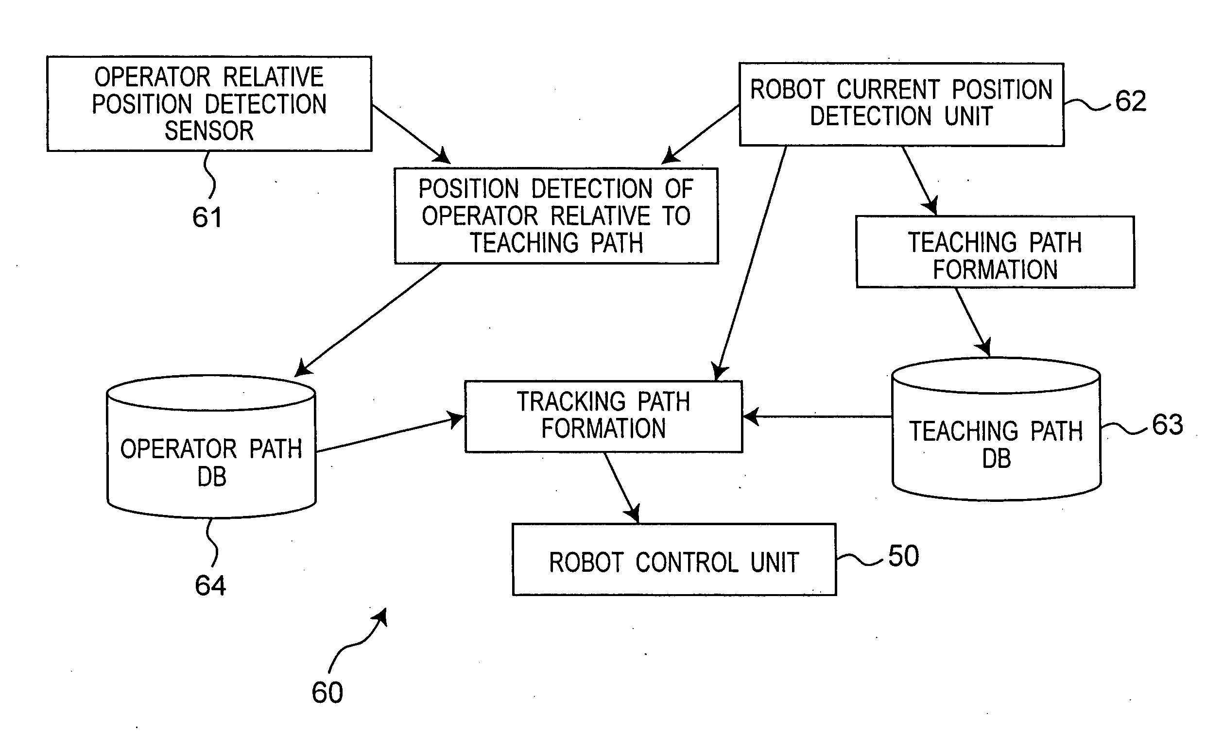
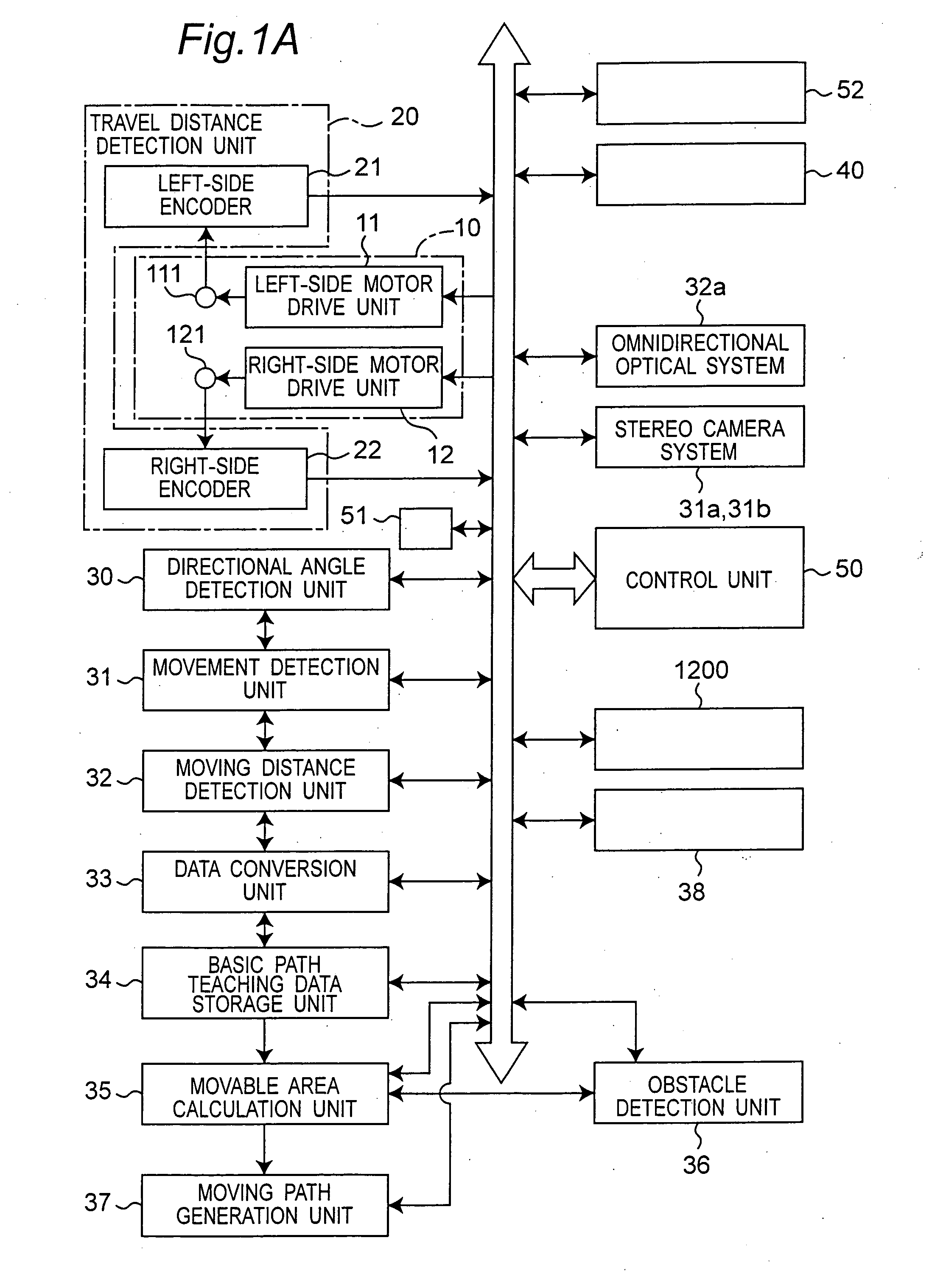
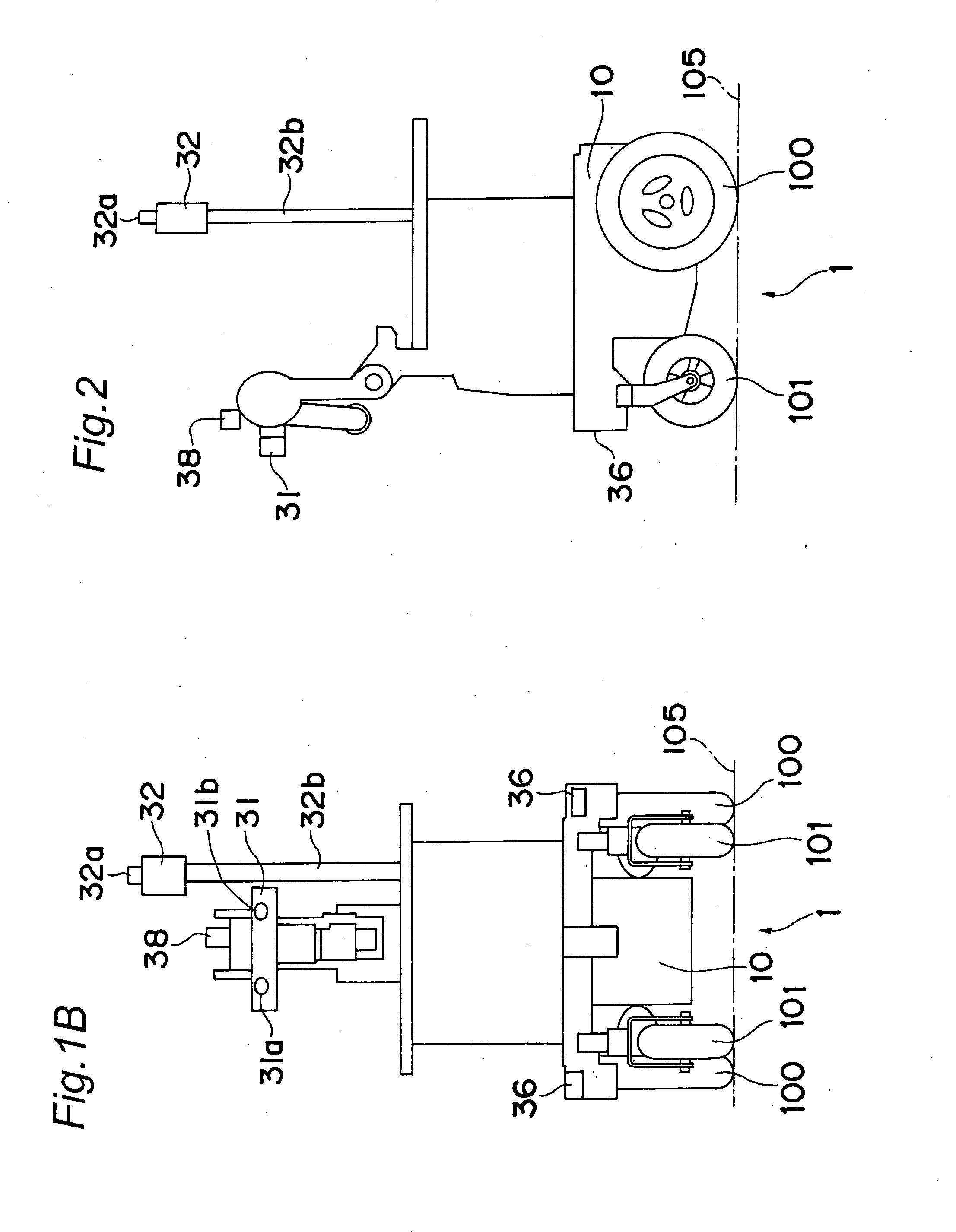
[0116]As shown in FIG. 1A, a robot control apparatus according to a first embodiment of the present invention is mounted on a robot 1, capable of traveling on a travel floor 105 of a large almost flat plane, for controlling movement of the mobile robot 1 forward and backward and in right and left sides. The robot control apparatus is configured to include, specifically, a drive unit 10, a travel distance detection unit 20, a directional angle detection unit 30, a human movement detection unit 31, a robot moving distance detection unit 32, a robot basic path teaching data conversion unit 33, a robot basic path teaching data storage unit 34, a movable area calculation unit 35, an obstacle detection unit 36, a moving path generation unit 37, and a control unit 50 for operation-controlling each of the drive unit 10 through the moving path generation unit 37.

[0117]The drive unit 10 is configured to include a left-side motor drive unit 11 for driving a left-side traveling motor 111 so as ...

second embodiment

[0155]Next, in a robot control apparatus and a robot control method according to a second embodiment of the present invention, a mobile body detection device (corresponding to the human-moving detection unit 31) for detecting a mobile body and a mobile body detection method will be explained in detail with reference to FIGS. 12A to 18D. Note that a “mobile body” mentioned here means a human, an animal, an apparatus moving automatically (autonomously mobile robot, autonomous travel-type cleaner, etc.), or the like. Further, a mobile body detection device 1200 is newly added to the robot control apparatus according to the first embodiment (see FIG. 1A), but the components of a part thereof may also work as components of the robot control apparatus according to the first embodiment.

[0156]The mobile body detection device and the mobile body detection method use an optical flow.

[0157]Before explaining the mobile body detection device and the mobile body detection method, explanation of t...

third embodiment

[0190]Next, a robot positioning device and a robot positioning method of a robot control apparatus and a robot control method according to a third embodiment of the present invention will be explained in detail with reference to FIGS. 20A to 26. The robot control apparatus according to the third embodiment described below is one newly added to the robot control apparatus according to the first embodiment, and a part of the components is also capable of serving as components of the robot control apparatus according to the first embodiment.

[0191]As shown in FIG. 20A, the robot positioning device of the robot control apparatus according to the third embodiment is configured to mainly include the drive unit 10, the travel distance detection unit 20, the directional angle detection unit 30, a displacement information calculation unit 40, and the control unit 50. Note that in FIG. 20A, components such as the movement detection unit 31 through the moving path generation unit 37, the teachi...


PUM


Abstract

In a robot control apparatus mounted on a mobile robot, movement of a human existing in front of the robot is detected, and the robot is moved in association with the movement of the human to thereby obtain path teaching data. When the robot moves autonomously according to the path teaching data, a robot movable area with respect to the path teaching data is calculated from positions of the ceiling and walls of the robot moving space or positions of obstacles detected by a surrounding object detection unit, whereby a moving path for autonomous movement is generated. The robot is controlled to move autonomously by a drive of a drive unit according to the moving path for autonomous movement.

Description

BACKGROUND OF THE INVENTION[0001]The present invention relates to a robot control apparatus which generates a path that an autonomous mobile robot can move while recognizing an area movable by the autonomous mobile robot through autonomous movement. The present invention relates to a robot control apparatus which generates a path that a robot can move while recognizing a movable area without providing a magnetic tape or a reflection tape on a part of a floor as a guiding path specifically, but providing an autonomous mobile robot with an array antenna and providing a human with a transmitter or the like to thereby detect a directional angle of the human existing in front of the robot time-sequentially and move the robot in association with the movement of the human with the human walking the basic path so as to teach the path, for example.[0002]In conventional art, map information prepared manually in detail is indispensable relating to a method of teaching a path of an autonomous m...

Claims


Application Information

Patent Timeline
Patent Type & Authority Applications(United States)
IPC IPC(8): G05B19/04
CPCG05D1/0221G05D1/0251G05D1/0253G05D2201/0215G05D1/027G05D1/0272G05D1/0274G05D1/0255
Inventor ANEZAKI, TAKASHI
Owner PANASONIC CORP
Why Eureka
Try Eureka