
Valve keeper installation tool

a technology for installing tools and valve keepers, which is applied in the direction of metal working tools, metal pliers, metal working tools, etc., can solve the problems of increased labor, increased labor, and difficulty in reaching the stems and springs, so as to facilitate the installation of two-part valve keepers, facilitate the installation of keeper, and minimize the effect of magnetic attraction

Inactive Publication Date: 2010-09-09
JENKS HAROLD
View PDF11 Cites 5 Cited by
  • Summary
  • Abstract
  • Description
  • Claims
  • Application Information

AI Technical Summary

Benefits of technology

[0010]The invention is a hand-held, valve keeper tool that facilitates the installation of the two-part valve keepers in an internal combustion engine. The pliers for installing a pair of valve keepers into an engine comprise jaws and handles with a pivot point therebetween, at least two grasping pins per keeper project outwardly from a shoulder stop at a terminal end of each jaw, the pins adapted to abut an outer surface of a valve keeper, and at least one magnet substantially flush with each shoulder stop for engaging an end of a keeper, the magnet adapted to releasably retain a keeper in contact with its grasping pins while minimizing the magnetic attraction between the pins and the engine. Thus, each keeper is retained in contact with its magnets and pins without requiring grip pressure to retain it in place allowing easier insertion of the keeper, particularly in cases where the keeper has more than one circumferential groove.

Problems solved by technology

In certain types of engines the valve stems and the stem surrounding springs are positioned in indentations or sockets in the block or cylinder head of the engine so that it may be difficult to reach the stems and springs and properly position the retainers in operating position when installing the valve assemblies in the engine.
This task is difficult under the best of circumstances, but it is even more difficult when there is more than one circumferential groove in the valve stem.
A particular problem is encountered using existing tools to try to place valve keepers with multiple circumferential grooves.
These makeshift solutions to the problem have been difficult and time-consuming resulting in frustration for the mechanic and additional costs for the person whose engine is being repaired.
An additional problem with prior tools for installation of valve keepers is that many were designed to operate with a specific size of valve keeper.
There was no way to accommodate a variety of sizes of keepers.

Method used


Image

  • Valve keeper installation tool
  • Valve keeper installation tool
  • Valve keeper installation tool

Examples


Embodiment Construction

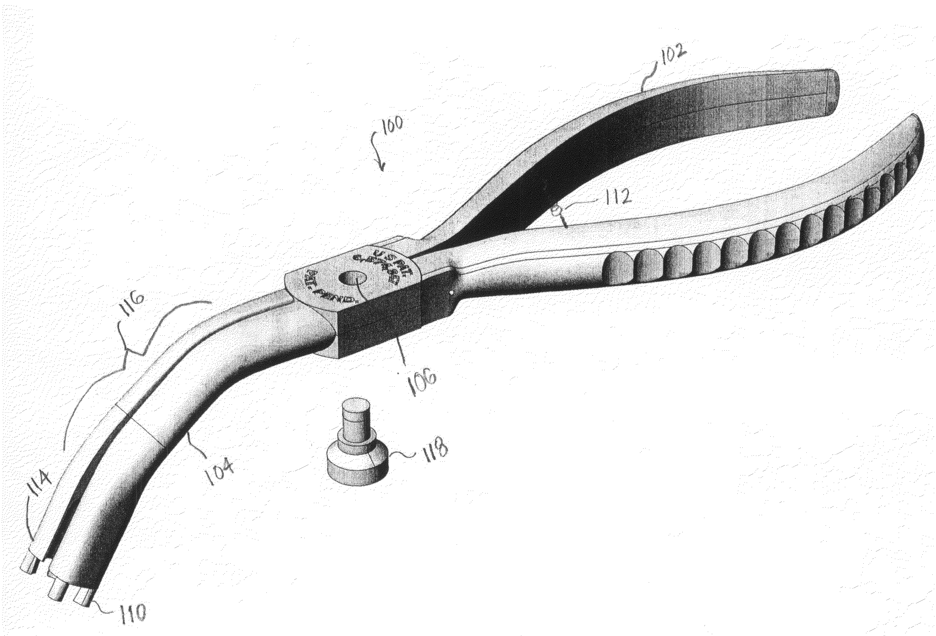
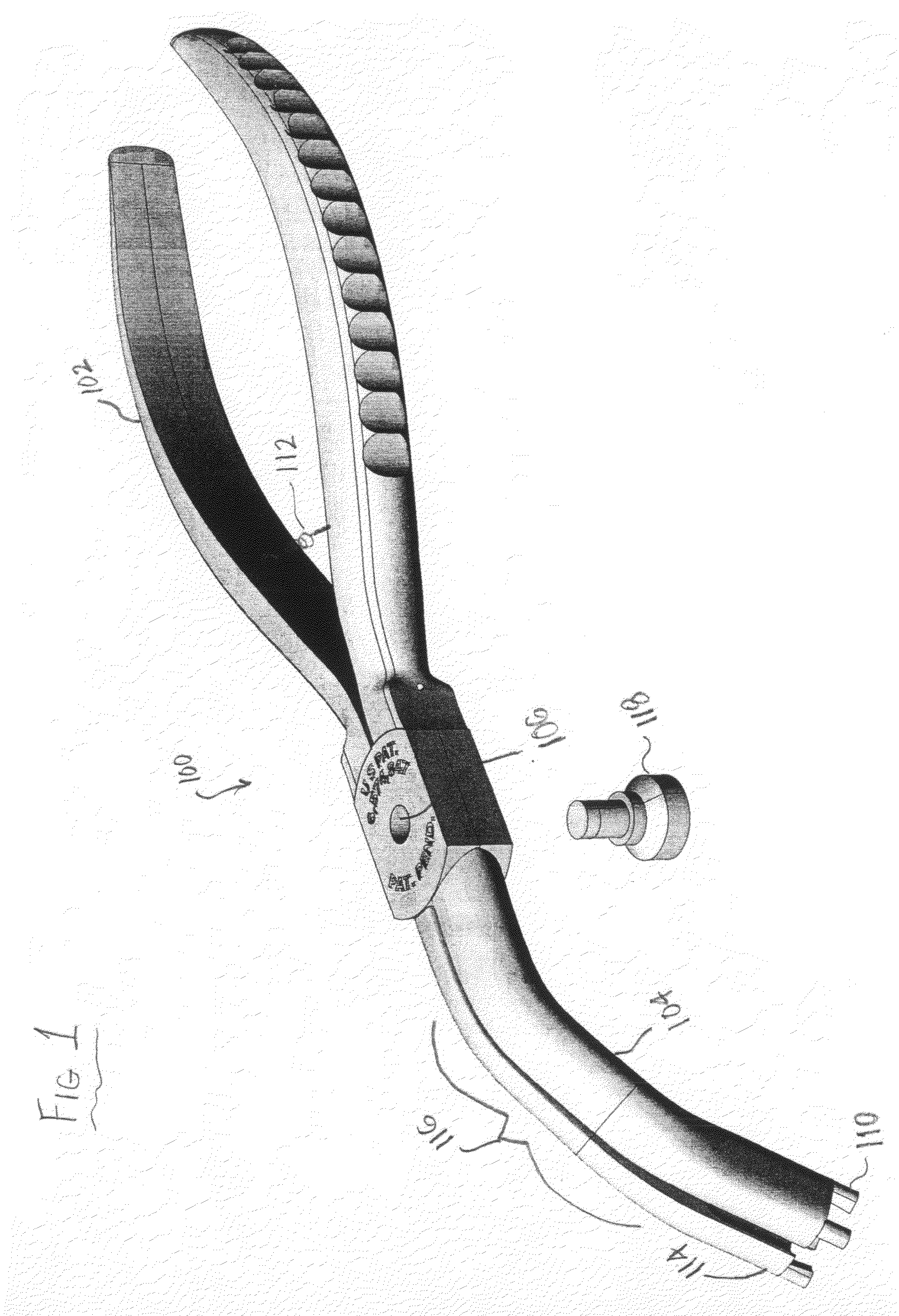
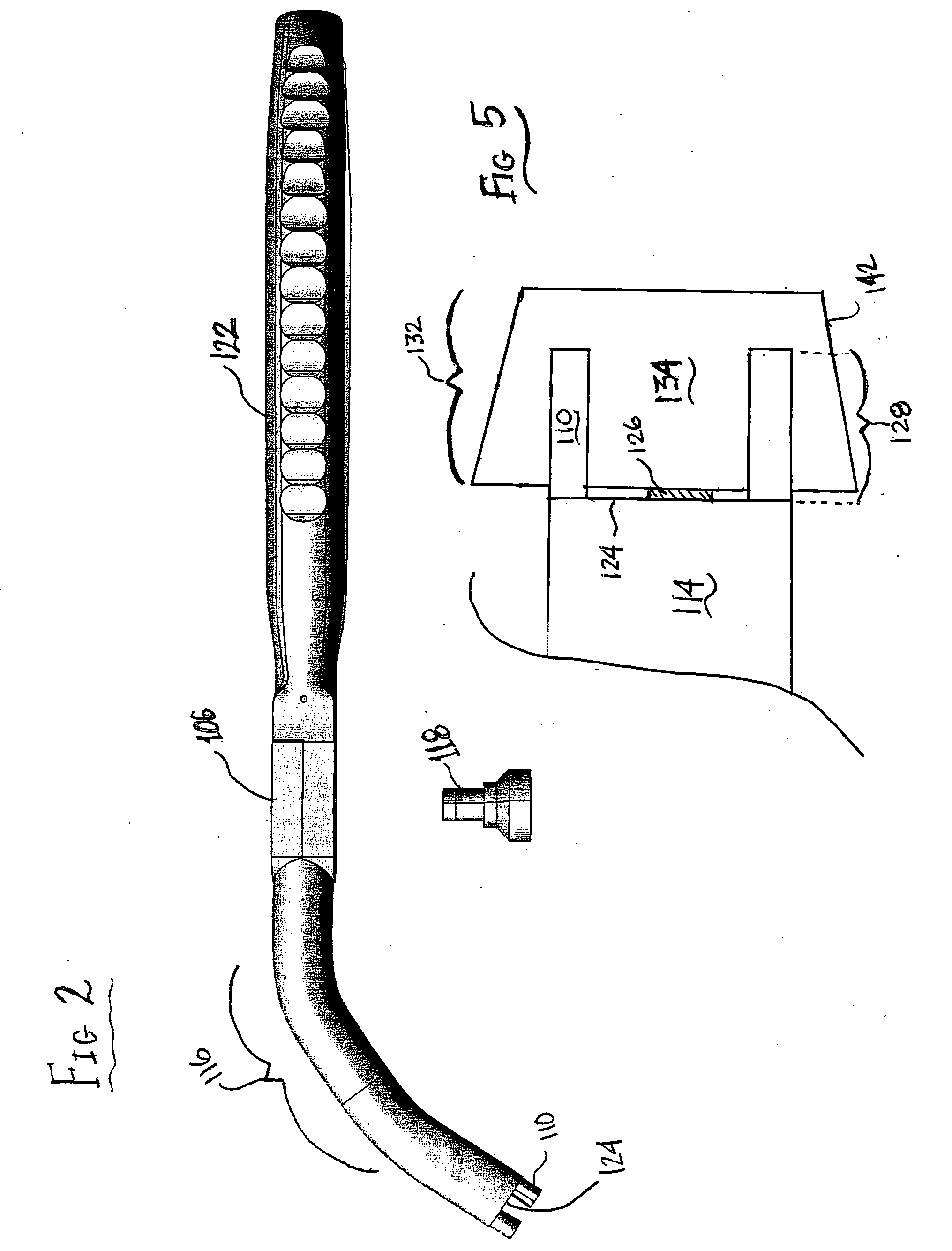
[0022]FIG. 1 shows a tool / pliers 100 according to the present invention. The pliers 100 have the standard components of handles 102, jaws 104, and a pivot point therebetween 106. The jaws 104 preferably have a bent portion 116 offset from a plane created by the handles 102. The bent portion 116 can be seen more easily in the side view shown in FIG. 2. At jaw ends 114 there are mounted at least two grasping pins 110 on each jaw 104. The grasping pins 110 contact the sides of a valve keeper 134 and, since they are not inherently shaped to mate with the back of a particular size of keeper, they can accommodate a wide range of keeper sizes. The pair of grasping pins 110 on each can be seen in FIG. 3 protruding from the shoulder stop 124 to which they are attached and within which the magnet 126 is inserted.

[0023]A biasing means 112 for urging the jaws 104 in an open direction is shown in FIG. 1. The purpose of the biasing means 112 is to allow the user to more easily operate the pliers ...


PUM

PropertyMeasurementUnit
Lengthaaaaaaaaaa

Abstract

Valve keeper pliers that facilitate the installation of the two-part valve keepers in an internal combustion engine, the pliers comprising jaws and handles with a pivot point therebetween, at least two grasping pins per keeper projecting outwardly from a shoulder stop at a terminal end of each jaw, the pins adapted to abut an outer surface of a keeper, and at least one magnet substantially flush with each shoulder stop for engaging an end of a keeper, the magnet adapted to releasably retain a keeper in contact with its grasping pins while minimizing the magnetic attraction between the pins and the engine, whereby each keeper is retained in contact with its magnets and pins without requiring grip pressure to retain it in place allowing easier insertion of the keeper, particularly in cases where the keeper has more than one retention groove. The jaws are preferably offset from a plane created by the handles to facilitate reaching into the locations where the valve keepers must be installed. A spring means for biasing the jaws in an open direction is preferably provided. The pliers may be made from a substantially non-magnetic material whereby the tendency of the pins to be magnetically drawn toward the engine is minimized.

Description

RELATED APPLICATIONS[0001]None.BACKGROUND[0002]A. Field of the Invention[0003]The invention relates to tools associated with engine repair, specifically to tools associated with installation of valve keepers.[0004]B. Related Art[0005]The springs on the intake and exhaust valves of conventional internal combustion engines act against spring washers which are detachably locked to the stems of the valves by means of split, conical valve keepers which interfit the spring washers and engage at least one circumferential groove in the stem of the valve to retain the spring washer in place against the expansive pressure of the spring. In certain types of engines the valve stems and the stem surrounding springs are positioned in indentations or sockets in the block or cylinder head of the engine so that it may be difficult to reach the stems and springs and properly position the retainers in operating position when installing the valve assemblies in the engine.[0006]When installing the keepe...

Claims


Application Information

Patent Timeline
IPC IPC(8): B23P19/04B25B7/02
CPCB25B7/02B25B27/0035B25B27/24Y10T29/53813Y10T29/53557Y10T29/53587Y10T29/53943Y10T29/539
Inventor JENKS, HAROLD
Owner JENKS HAROLD
Learn More