Chip deflector on a blade of a downhole reamer and methods therefore

a technology of expandable reamer and blade, which is applied in the direction of drilling machine, cutting machine, construction, etc., can solve the problems of expensive pistons, high cost, and inability to help blade retraction, and achieve the effect of enlarge the borehole diameter

Inactive Publication Date: 2010-09-09
BAKER HUGHES INC
View PDF101 Cites 58 Cited by
  • Summary
  • Abstract
  • Description
  • Claims
  • Application Information

AI Technical Summary

Problems solved by technology

While adding additional casing allows a borehole to reach greater depths, it has the disadvantage of narrowing the borehole.
Also, designs of these conventional expandable reamer assemblies fail to help blade retraction when jammed and pulled upward against the borehole casing.
Furthermore, some conventional hydraulically actuated reamers utilize expensive seals disposed around a very complex shaped and expensive piston, or blade, carrying cutting elements.
These seals are feared to possibly leak after extended usage.
Relatively thin layers of hardfacing have been applied to relatively large areas where erosion and abrasion from cuttings, high-velocity fluid and contact with the formation causes undesirable wear on the bit.
Steel body bits tend to exhibit superior toughness but limited erosion and abrasion resistance, whereas matrix bits tend to exhibit reduced toughness but exemplary erosion and abrasion resistance.
However, use of hardfacing material as taught by Radtke et al. does not address issue of material toughness as may be required for various portions of the bit while also exploiting the advantages of an abrasion-resistant material.
However, Smith et al. does not address strategic localization of a material according to its characteristics of either abrasion resistance or material toughness.
Smith et al. fail to particularly address such issues with regard to a steel body bit.
Chip breakers in steel body bits may be machined into the surface of the bit; however, this too may place limits on the bit design.
Although sintered carbide cylinders function adequately as a drill bit gage, the necessity of milling precise holes for press fitting is cumbersome and limits the configuration of the gage.
In addition, sintered carbide gage cylinders often exhibit cracking after use, referred to as crazing, perhaps attributable to the extreme heating and cooling cycles present during drilling conditions.

Method used


Image

  • Chip deflector on a blade of a downhole reamer and methods therefore
  • Chip deflector on a blade of a downhole reamer and methods therefore
  • Chip deflector on a blade of a downhole reamer and methods therefore

Examples


Embodiment Construction

[0052]The illustrations presented herein are, in some instances, not actual views of any particular reamer tool, cutting element, or other feature of a reamer tool, but are merely idealized representations that are employed to describe the present invention. Additionally, elements common between figures may retain the same numerical designation.

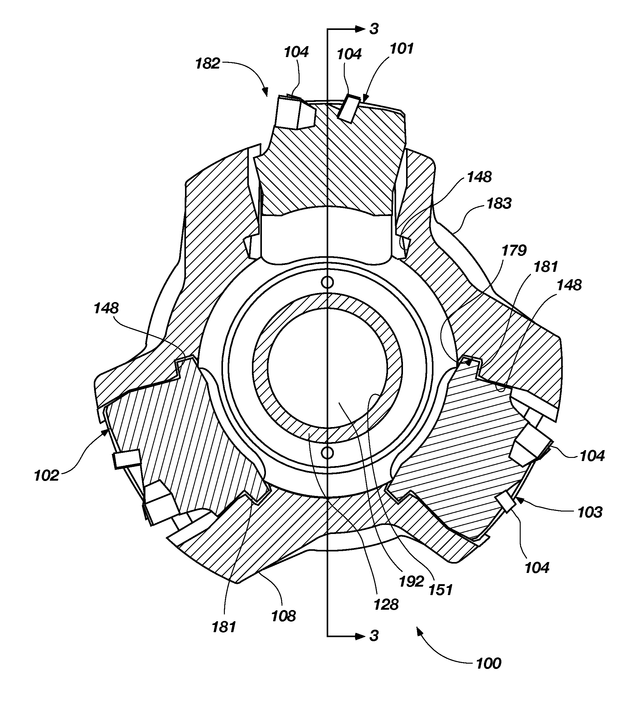
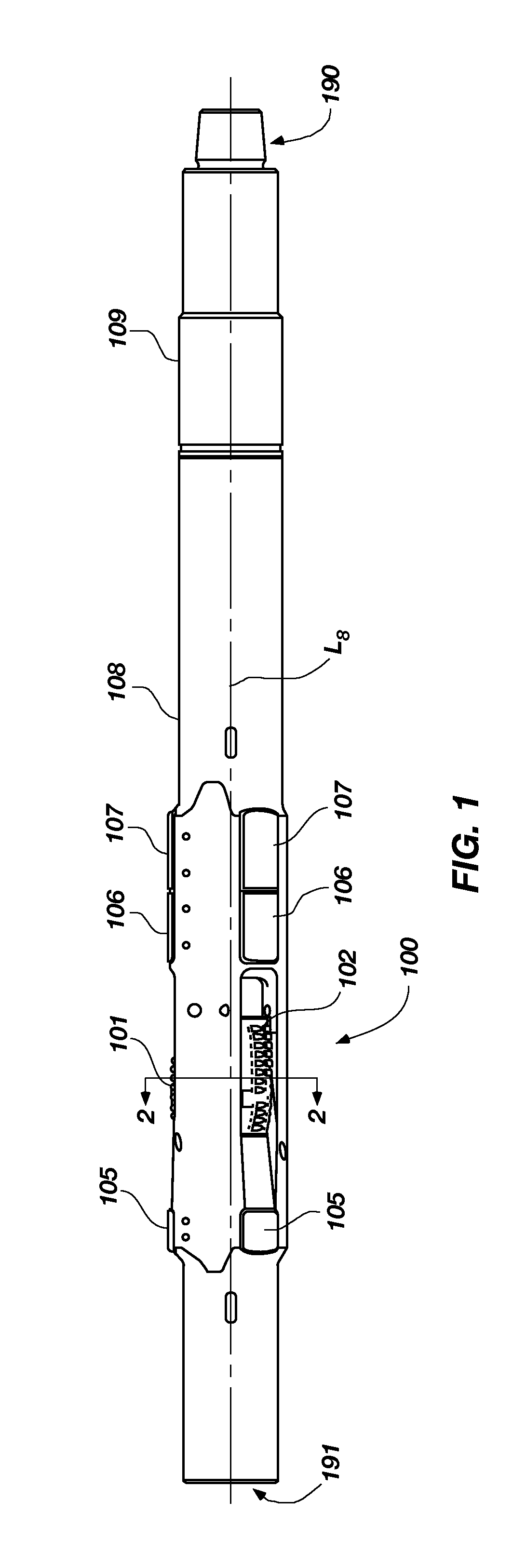
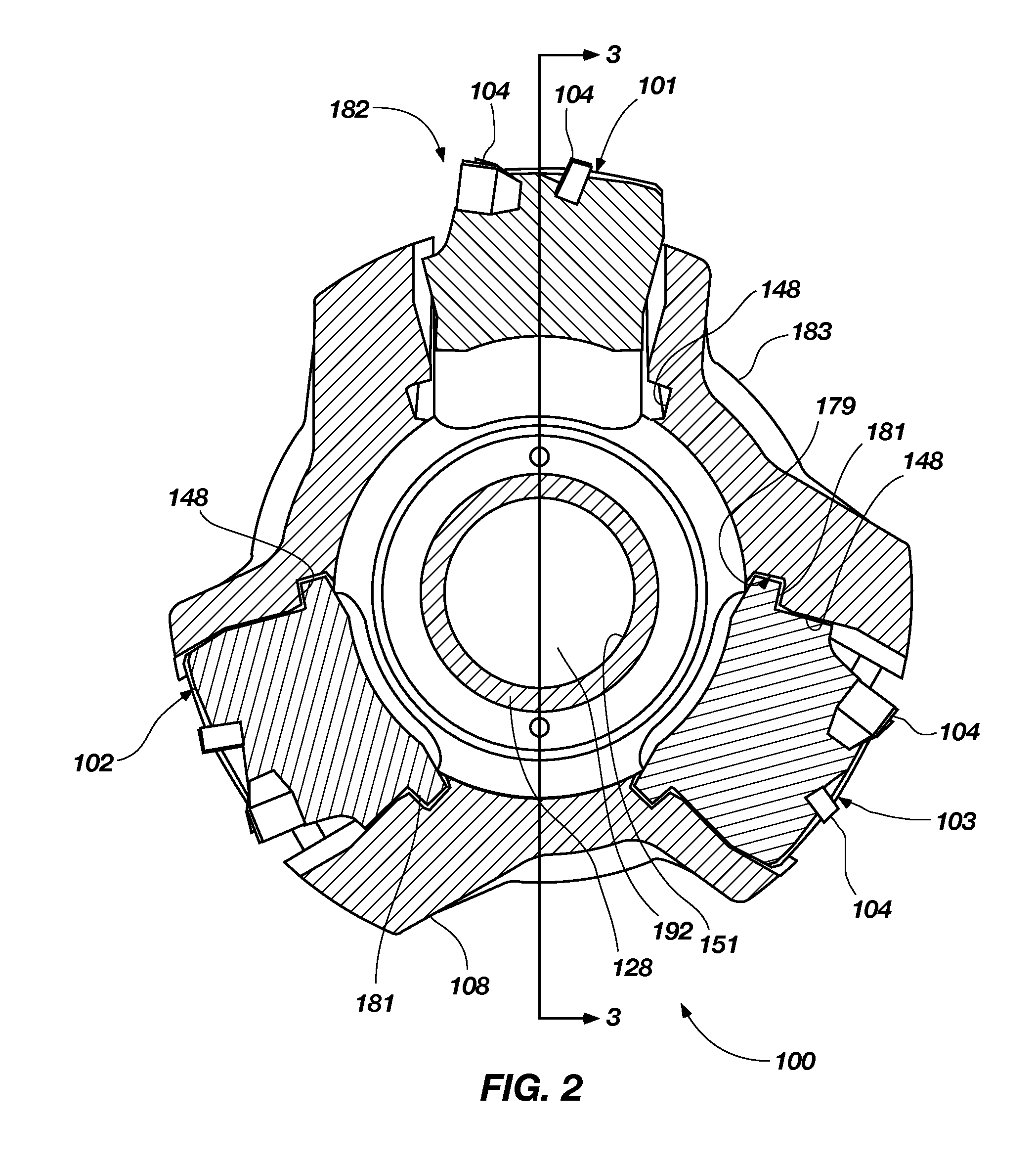
[0053]An expandable reamer apparatus 100 according to an embodiment of the invention is shown in FIG. 1. The expandable reamer apparatus 100 may include a generally cylindrical tubular body 108 having a longitudinal axis L8. The tubular body 108 of the expandable reamer apparatus 100 may have a lower end 190 and an upper end 191. The terms “lower” and “upper,” as used herein with reference to the ends 190, 191, refer to the typical positions of the ends 190, 191 relative to one another when the expandable reamer apparatus 100 is positioned within a well bore. The lower end 190 of the tubular body 108 of the expandable reamer apparatus 100 may...


PUM


Abstract

An expandable reamer apparatus for drilling a subterranean formation includes a tubular body, one or more blades, each blade positionally coupled to a sloped track of the tubular body having a hardfacing material on a portion thereof, a push sleeve and a drilling fluid flow path extending through an inner bore of the tubular body for conducting drilling fluid therethrough.

Description

[0001]This application is a utility conversion of U.S. Provisional Application Ser. No. 61 / 156,936, filed Mar. 3, 2009, for “CHIP DEFLECTOR ON A BLADE OF A DOWNHOLE REAMER AND METHODS THEREFOR,” the entire disclosure of which is hereby incorporated herein by this reference.TECHNICAL FIELD[0002]The present invention relates generally to improved blades for an expandable reamer apparatus for drilling a subterranean borehole and, more particularly, to improved blades for an expandable reamer apparatus for enlarging a subterranean borehole beneath a casing or liner.BACKGROUND[0003]Expandable reamers are typically employed for enlarging subterranean boreholes. Conventionally in drilling oil, gas, and geothermal wells, casing is installed and cemented to prevent the well bore walls from caving into the subterranean borehole while providing requisite shoring for subsequent drilling operations to achieve greater depths. Casing is also conventionally installed to isolate different formations...

Claims


Application Information

Patent Timeline
Patent Type & Authority Applications(United States)
IPC IPC(8): E21B7/00E21B10/26
CPCE21B2010/566E21B10/322E21B10/5671
Inventor RADFORD, STEVEN R.KIDDER, KEVIN G.
Owner BAKER HUGHES INC
Why Eureka
Try Eureka