Electron Microscope

a transmission electron microscope and electron microscope technology, applied in the direction of material analysis using wave/particle radiation, instruments, nuclear engineering, etc., can solve the problems of complicated adjustment of the whole electron optical system, difficulty in minute adjustment of the angular aperture, etc., and achieve the effect of easy correction of aberrations

Active Publication Date: 2010-09-09
JEOL LTD
View PDF4 Cites 13 Cited by
  • Summary
  • Abstract
  • Description
  • Claims
  • Application Information

AI Technical Summary

Benefits of technology

[0008]It is an object of the present invention to provide an electron microscope permitting aberrations to be corrected easily even during high magnification imaging.

Problems solved by technology

Therefore, with aperture stops differing greatly in hole diameter as described previously, it is difficult to adjust the angular aperture minutely.
This complicates the adjustment of the whole electron optical system.

Method used


Image

  • Electron Microscope
  • Electron Microscope
  • Electron Microscope

Examples


Embodiment Construction

[0020]The preferred embodiments of the present invention are hereinafter described with reference to the drawings. In the following description, a scanning transmission electron microscope (STEM) is taken as one example of the used electron microscope. The present invention can also be applied to transmission electron microscopes (TEMs) and scanning electron microscopes (SEMs).

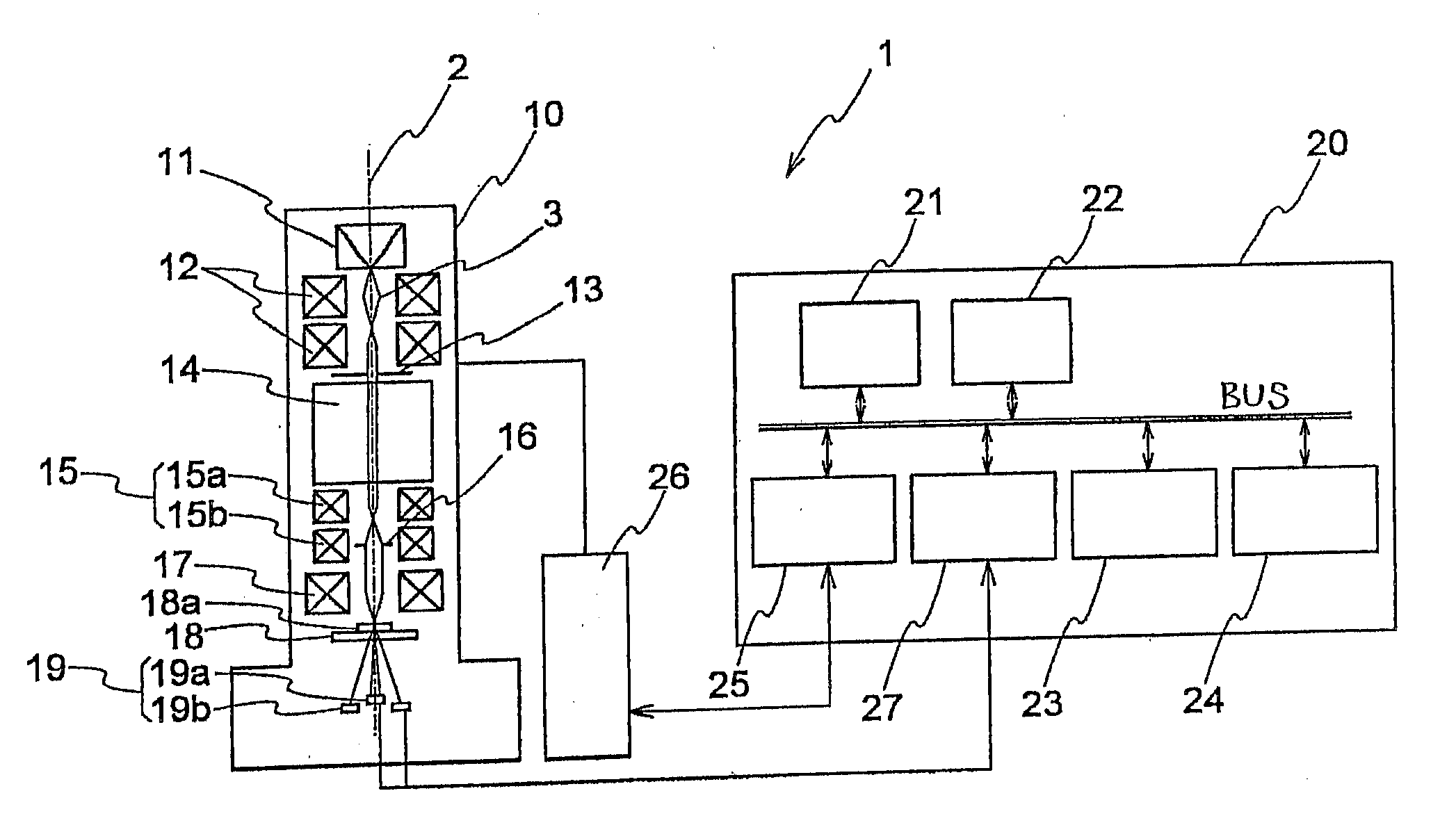
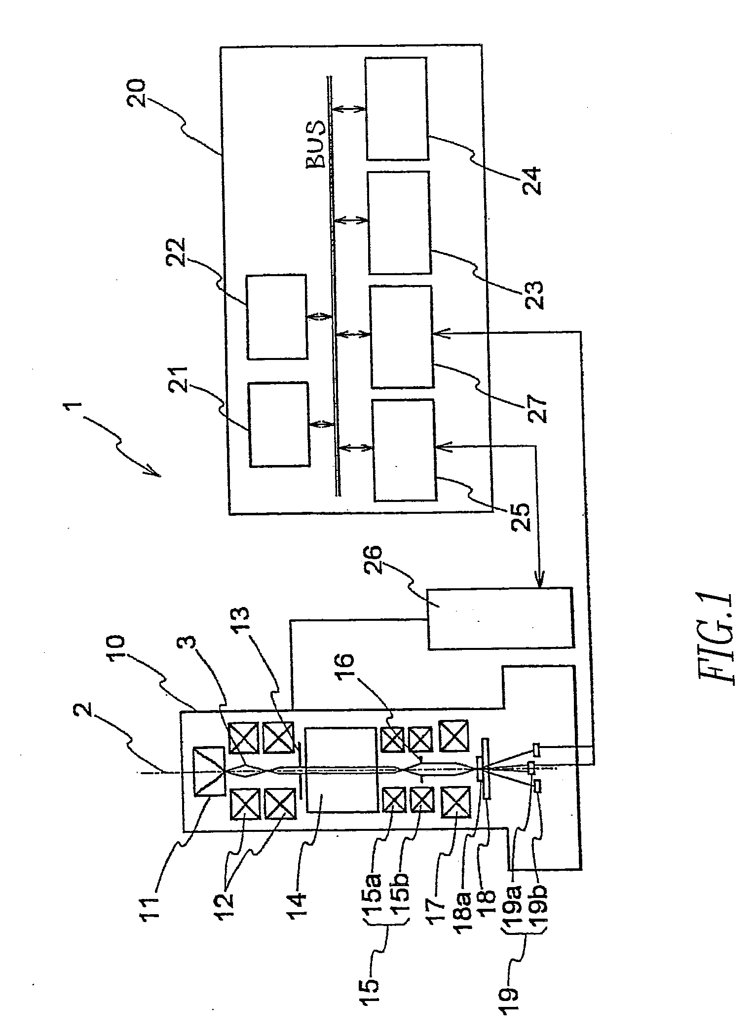
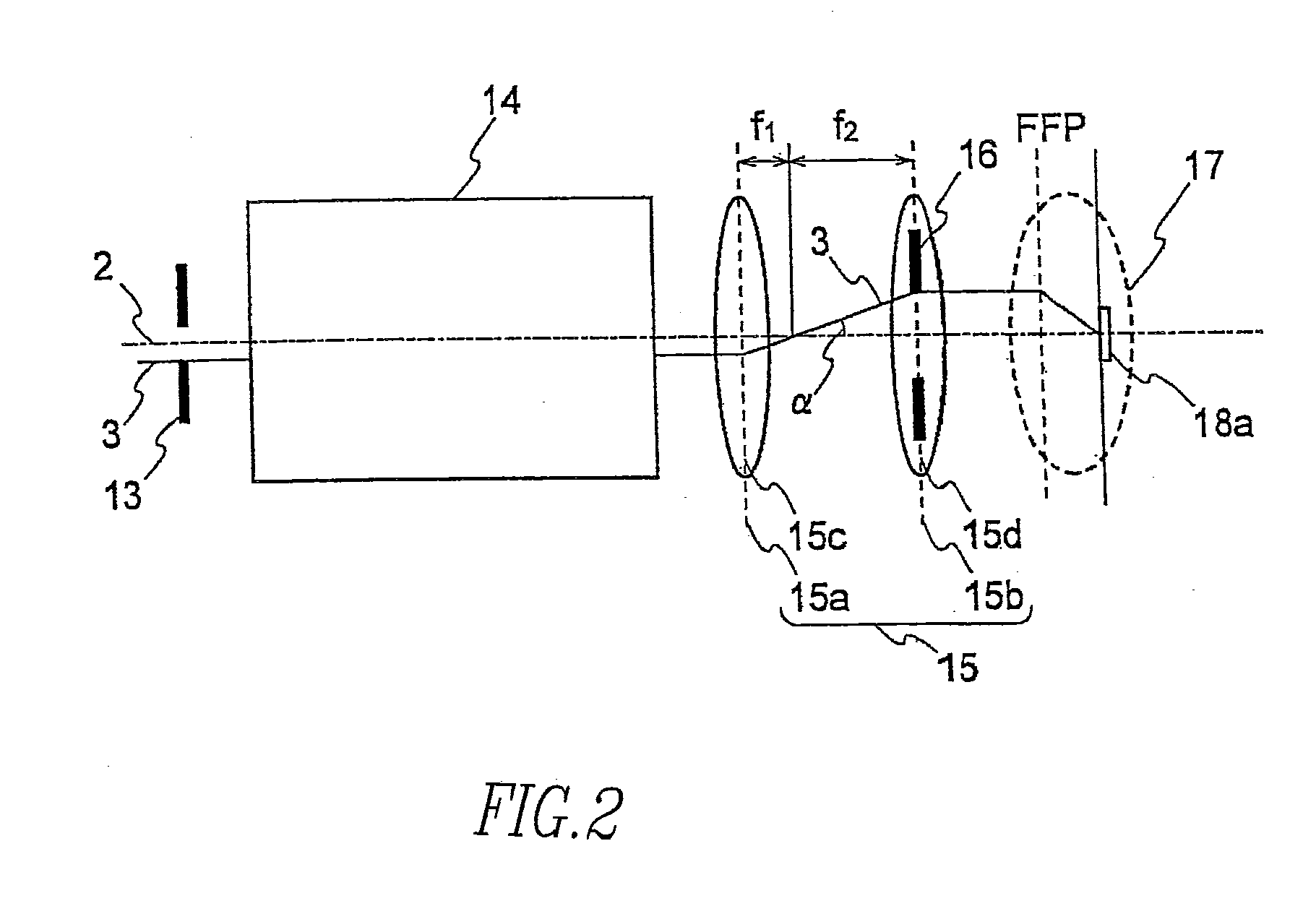
[0021]FIG. 1 is a schematic diagram showing a scanning transmission electron microscope associated with one embodiment of the present invention, the microscope being indicated by reference numeral 1. FIG. 2 is a schematic diagram showing the arrangement of an angular aperture stop associated with one embodiment of the invention.

[0022]The scanning transmission electron microscope 1 is chiefly comprised of a microscope body 10 and a control unit 20 for controlling an electron optical system installed in the body 10. An electron gun 11 for emitting an electron beam 3 is installed within the electron optical colum...


PUM

PropertyMeasurementUnit
diametersaaaaaaaaaa
hole diametersaaaaaaaaaa

Abstract

An electron microscope is offered which facilitates aberration correction even during high-magnification imaging. The microscope has a spherical aberration corrector, a transfer lens system mounted between the corrector and an objective lens, an aperture stop mounted in a stage preceding the corrector so as to be movable relative to the optical axis, and an angular aperture stop mounted at or near the principal plane of the transfer lens system movably relative to the optical axis to adjust the angular aperture of the electron beam.

Description

BACKGROUND OF THE INVENTION[0001]1. Field of the Invention[0002]A prior art scanning transmission electron microscope has aperture stops to control the emission current and illumination angle of the electron beam relative to a specimen. The aperture stops are movably mounted near the principal plane of a condenser lens (brightness-adjusting lens) immediately behind the electron source. Usually, plural aperture stops having different hole diameters are used for the above-described control operations. The aperture stops are mounted to a stop holder having a moving mechanism. Because the aperture stops are close to the principal plane of the condenser lens, if the strength of the condenser lens is varied while one aperture stop is in operation, the total amount of current impinging on the specimen does not vary so much.[0003]2. Description of Related Art[0004]In the case of an electron microscope employing no aberration correction technique, the necessity to controllably vary the angul...

Claims


Application Information

Patent Timeline
Patent Type & Authority Applications(United States)
IPC IPC(8): G01N23/02
CPCH01J37/023H01J37/09H01J37/153H01J37/28H01J2237/2823H01J2237/0458H01J2237/1534H01J2237/2802H01J2237/0453
Inventor HOSOKAWA, FUMIO
Owner JEOL LTD
Why Eureka
Try Eureka