Spindle with hydraulic passage arrangement and method of manufacture

Active Publication Date: 2010-09-09
TERRA DRIVE SYST
View PDF17 Cites 21 Cited by
  • Summary
  • Abstract
  • Description
  • Claims
  • Application Information

AI Technical Summary

Benefits of technology

[0006]The present invention provides a spindle body having a plurality hydraulic passages t

Problems solved by technology

This arrangement of the hydraulic passages, while effectively communicating hydraulic fl

Method used


Image

  • Spindle with hydraulic passage arrangement and method of manufacture
  • Spindle with hydraulic passage arrangement and method of manufacture
  • Spindle with hydraulic passage arrangement and method of manufacture

Examples


Embodiment Construction

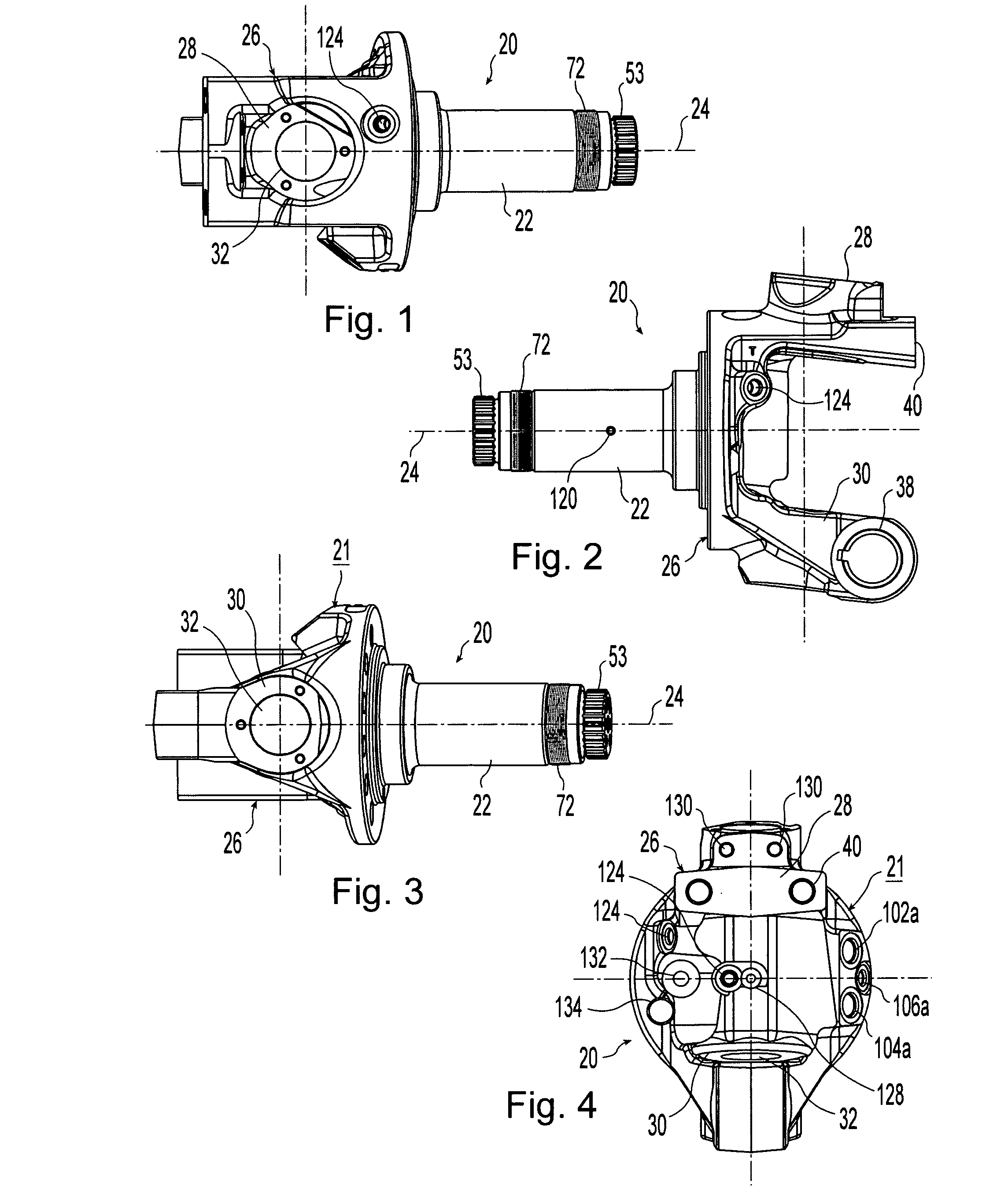
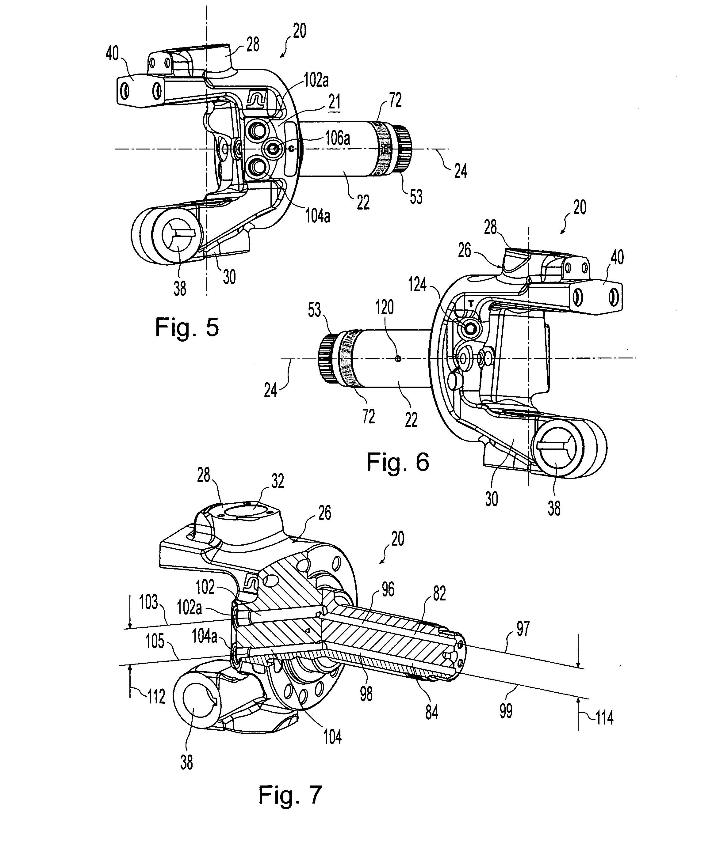
[0028]A spindle body 20 is shown in FIGS. 1-8. Spindle body 20 includes a spindle shaft 22 defining a central axis 24 and a knuckle portion 26. Knuckle 26 includes an upper projection 28 and a lower projection 30 which have aligned bore holes 32 for rotatably receiving a king pin 34. King pin 34 rotatably secures spindle body 20 to a vehicle structure 36 (FIG. 11).

[0029]Knuckle 26 also defines a tie rod mounting bore 38. Spindle 20 is adapted to support a steerable wheel and includes holes on a mounting interface 40 for connecting knuckle 26 to a vehicle steering arm (not shown), bores 130 for mounting a hose guide bracket, a steering stop bore 132 and a bore 134 for receiving an ABS sensor. Mounting holes 126 (FIG. 8) are used to secure a brake assembly to spindle body 20.

[0030]A hydraulic motor assembly 42 is mounted on spindle shaft 22 (FIGS. 9-11 and 13). Hydraulic motor assembly 42 is a conventional hydraulic motor that can be mounted within a wheel hub. Motor assembly 42 inclu...


PUM


Abstract

A spindle body defining a central axis and having a hydraulic motor assembly operably mounted thereon. At least a portion of the hydraulic motor assembly is rotatable relative to the spindle body about the central axis. A plurality of hydraulic passages extend within the spindle body. Each of the passages includes axial and lateral sections. The axial sections are in fluid communication with the hydraulic motor assembly and define a first centerline extending substantially parallel with the central axis. Each of the lateral sections are in fluid communication with one of the axial sections and form a port on an outer surface of the spindle body. The lateral sections also each define a second centerline wherein the second centerlines are positioned in mutually parallel planes and each of the first centerlines and the central axis are substantially parallel with each of the mutually parallel planes. A method of manufacture is also disclosed.

Description

BACKGROUND OF THE INVENTION[0001]1. Field of the Invention[0002]The present invention relates to hydraulic motor assemblies and, more particularly, to hydraulic motor assemblies mounted within a wheel and rotatably carried on a spindle.[0003]2. Description of the Related Art[0004]The mounting of a hydraulic motor within a wheel wherein the hydraulic motor is rotatably carried on a spindle is known in the art. Typically, such hydraulic motors drive the rotation of the wheel within which they are mounted when the motor is operating and allow the wheel to freely rotate when the motor is not providing a driving force. The spindle is often integrally formed with a knuckle that can be rotatably engaged with a vertically extending kingpin. The rotatable engagement of the knuckle and kingpin allow the wheel to be a steerable wheel.[0005]Hydraulic fluid must be communicated to and from the hydraulic motor and hydraulic passages are typically formed in the spindle and knuckle to provide for t...

Claims


Application Information

Patent Timeline
IPC IPC(8): B60B35/02B21D53/26
CPCF16D31/02Y10T29/49487F16D2250/00
Inventor KIRBY, LANE C.
Owner TERRA DRIVE SYST
Why Eureka
Try Eureka