

Coin dispenser
a dispenser and coin technology, applied in the field of coin dispensers, can solve the problems of inability to allow vertical growth, inconvenience of high volume compared to the obtained capacity, and the mechanism is not suitable for individual coin transportation
- Summary
- Abstract
- Description
- Claims
- Application Information
AI Technical Summary
Benefits of technology
Problems solved by technology
Method used
Image

Examples
Embodiment Construction
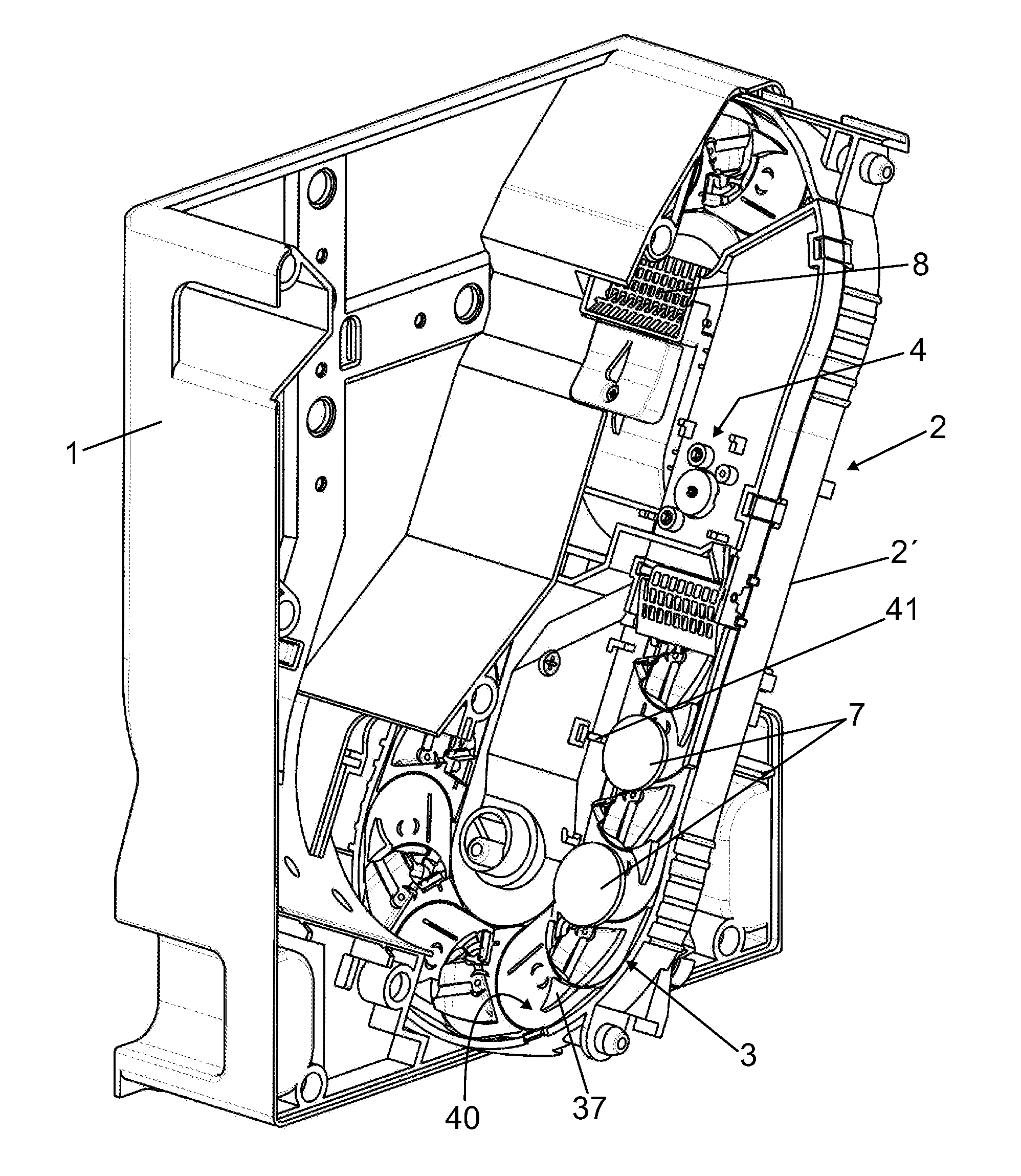
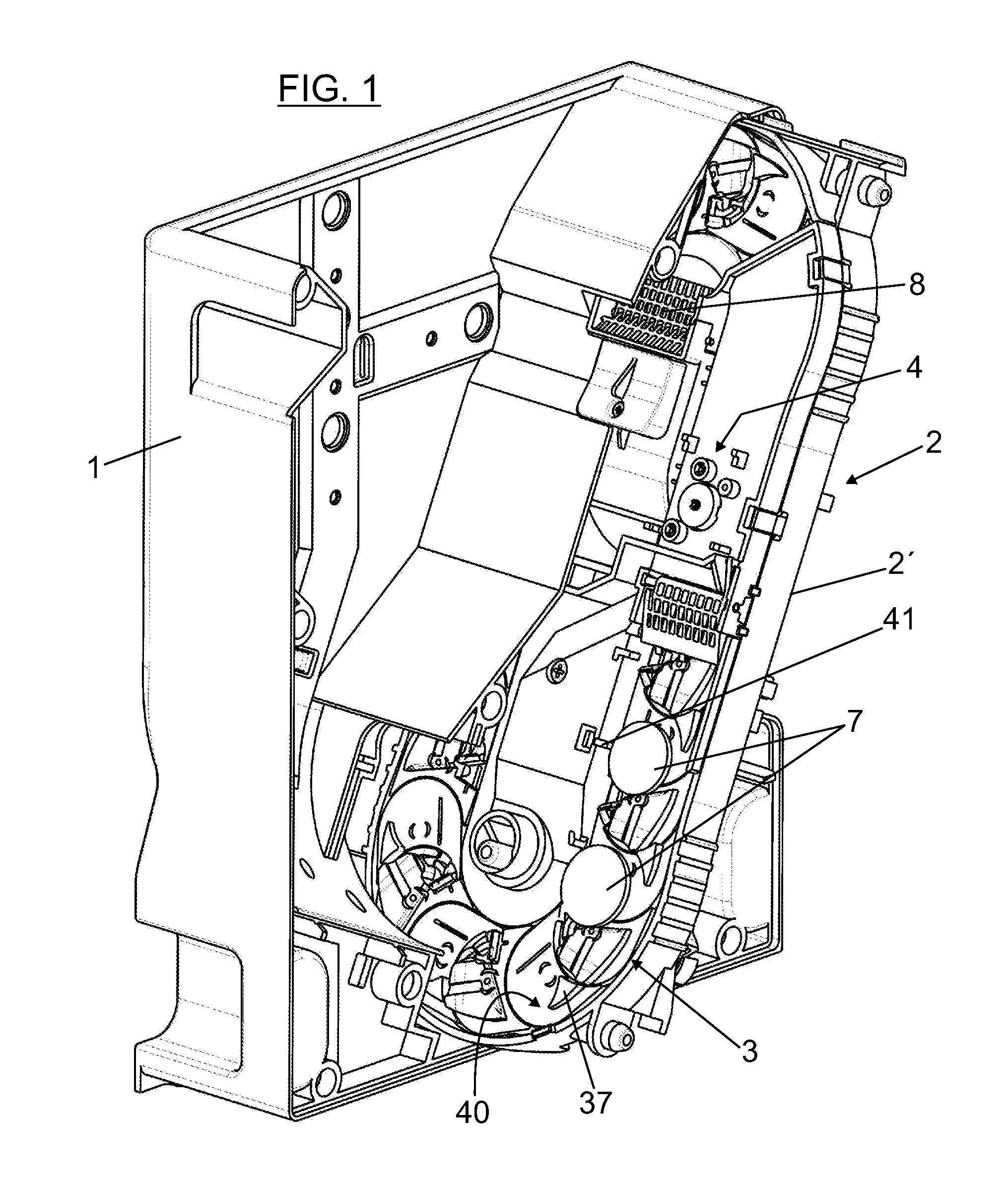
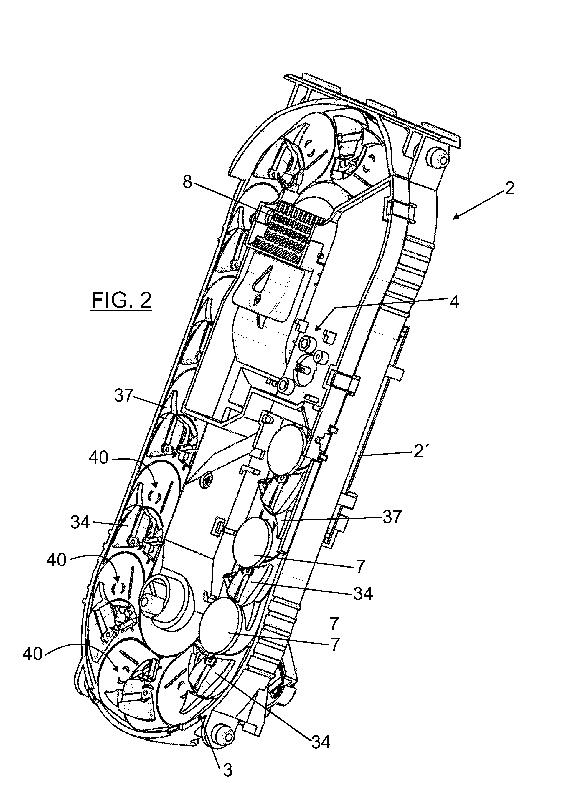
[0013]The object of the present invention is a coin dispenser, of the type previously stated, which offers great capacity to contain different value and dimension coins and presents proportionally reduced dimensions, enabling its use in applications in which the space occupied is a limitation. The coin dispenser of the invention is also of simple and robust construction, which also facilitates its use in the applications requiring low cost and high reliability, as is the case for example of parking lot ticket machines, vending machines, recreational machines or gambling machines, etc. The coin dispenser of the invention also enables, if necessary, to increase the capacity to contain coins through an increase of its vertical dimension.
[0014]Another advantage of the coin dispenser of the invention is that the coins that return to the storage unit can do so towards far-away positions to the point where they are collected by the extractor, thus enabling the arrival to the coin collectio...
PUM
 Abstract
Description
Claims
Application Information