Guided bridge for a piston in an internal combustion engine

a technology of internal combustion engine and guided bridge, which is applied in the direction of reciprocating piston engines, positive displacement engines, machines/engines, etc., can solve the problems of other undesirable effects, and achieve the effects of reducing friction, eliminating side forces, and increasing efficiency

Inactive Publication Date: 2010-09-16
ECOMOTORS INT +1
View PDF11 Cites 35 Cited by
  • Summary
  • Abstract
  • Description
  • Claims
  • Application Information

AI Technical Summary

Benefits of technology

[0017]It is an object of the present invention to provide an improved OPOC engine with reduced friction and increased efficiencies by eliminating side forces on the outer pistons during the engine cycle.
[0018]It is another

Problems solved by technology

However, each conventional attempt to reduce the effects of p

Method used


Image

  • Guided bridge for a piston in an internal combustion engine
  • Guided bridge for a piston in an internal combustion engine
  • Guided bridge for a piston in an internal combustion engine

Examples


Embodiment Construction

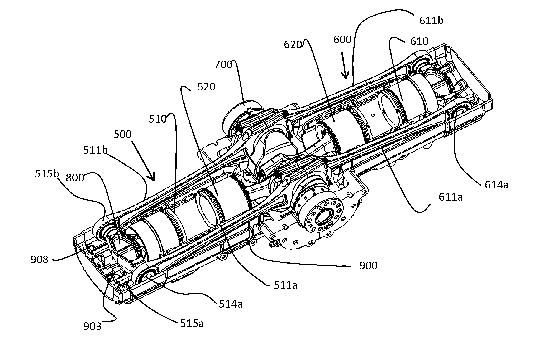
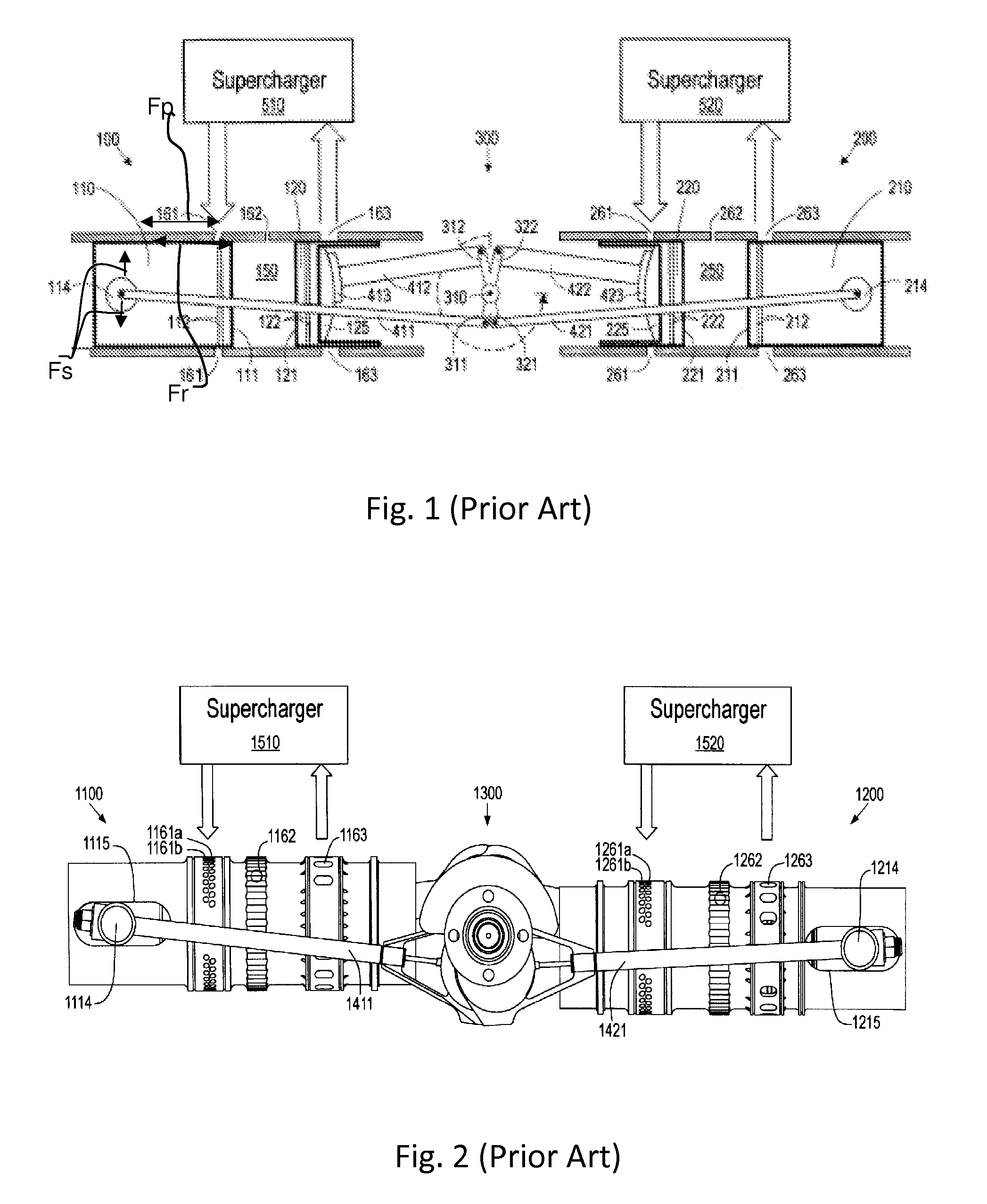
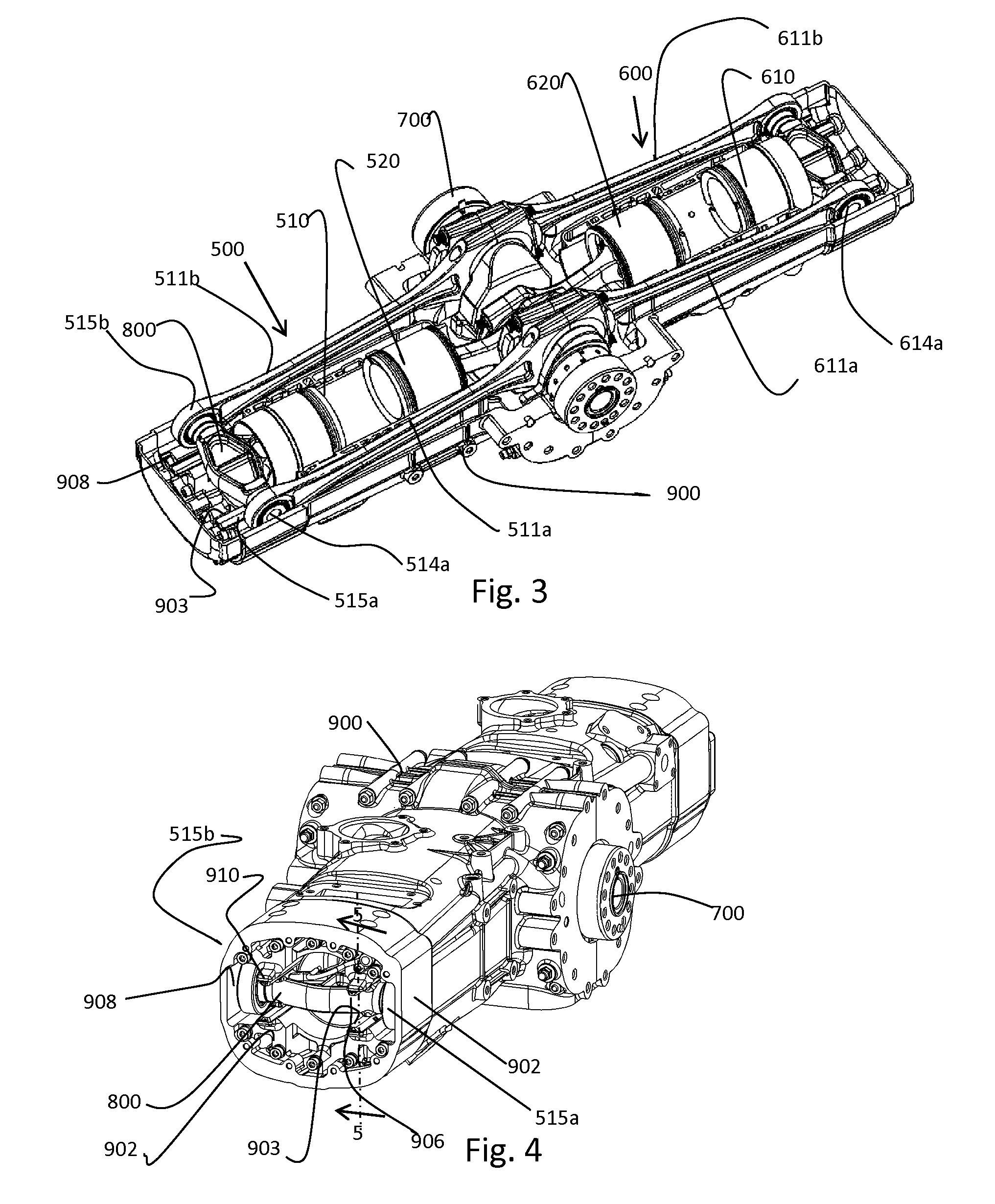
[0032]The present invention is shown in FIGS. 3-13, in conjunction with an OPOC engine of the type described above and incorporated herein by reference. In FIG. 3, an OPOC engine is shown as having a left cylinder 500, a right cylinder 600 in a housing 900 and a common crankshaft 700. Left cylinder 500 has an outer piston 510 and an inner piston 520. Opposing right cylinder 600 has an outer piston 610 and an inner piston 620. Outer piston 510 is connected to crankshaft 700 via a pair of pull rods 511a and 511b. Outer piston 610 is connected to the crankshaft 700 via a pair of pull rods 611a and611b.

[0033]The improvement over the prior art OPOC engine described above results from the use of a guided bridge 800 that is located between the outer piston 510 and the pullrods 511a and 511b. (Although the following discussion is directed to the left cylinder 500, it should be understood that the right cylinder is identically configured to provide identical improvements to the engine as a ...


PUM


Abstract

An improved configuration for internal combustion engine that reduces side forces on pistons during the engine cycle. The improvement is an intermediate and guided bridge element located between pull rods and pistons with articulated connections that allow side forces to be dissipated away from the pistons.

Description

RELATED APPLICATIONS[0001]This application claims priority benefit of provisional application Ser. No. 61 / 209,904, filed Mar. 12, 2009.TECHNICAL FIELD[0002]This invention is related to the field of internal combustion engines and more specifically to improvements in such engines configured with opposing cylinders and opposing pistons in each cylinder (“OPOC engine”).BACKGROUND[0003]This invention involves improvements to internal combustion engines and in particular OPOC engines of the type described and claimed in earlier U.S. Pat. Nos. 6,170,443, and 7,434,550, which are incorporated herein by reference. Other types of OPOC engines having one or more crankshafts, also can benefit from the present invention.[0004]As background, the OPOC engine from U.S. Pat. No. 6,170,443 is shown in FIGS. 1 and 2. In those figures, the engine configuration is shown to comprise a left cylinder 100 (1100FIG. 2), a right cylinder 200 (1200), and a single central crankshaft 300 (1300) located between ...

Claims


Application Information

Patent Timeline
IPC IPC(8): F02B75/28F02F3/00
CPCF01B7/14F02B75/28F02B75/243
Inventor HOFBAUER, PETERTUSINEAN, ADRIAN N.LEE, CHOU
Owner ECOMOTORS INT
Why Eureka
Try Eureka