Variable speed wind turbine having a constant speed generator

a variable speed, generator technology, applied in the direction of electric generator control, machines/engines, mechanical equipment, etc., can solve the problems of inconvenient use, rotor overspeed, and inability to produce power,

a variable speed, generator technology, applied in the direction of electric generator control, machines/engines, mechanical equipment, etc., can solve the problems of inconvenient use, rotor overspeed, and inability to produce power,

US20100230966A1Inactive Publication Date: 2010-09-16PAVLAK ALEXANDER J

Image

  • Variable speed wind turbine having a constant speed generator
  • Variable speed wind turbine having a constant speed generator
  • Variable speed wind turbine having a constant speed generator

Examples


Embodiment Construction

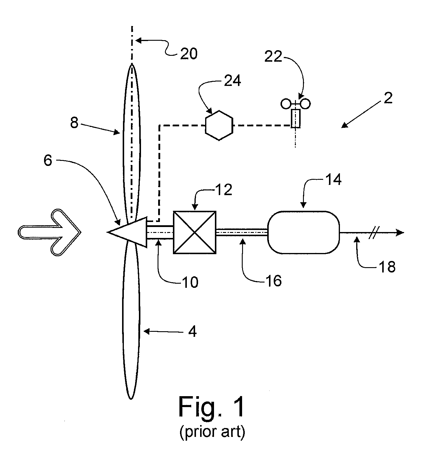
[0031]Referring first to FIG. 1, there is shown the power train 2 for a constant speed wind turbine according to the prior art. The power train includes a wind driven rotor 4 including a hub 6 and a plurality of blades 8 extending radially therefrom. A low speed high torque rotor shaft 10 is connected at one end with the hub and at the other end with a fixed ratio gearbox 12. The gearbox drives a generator 14 through a high speed low torque shaft 16. The generator provides constant frequency AC power directly to an electrical grid 18.

[0032]Each rotor blade 8 has an axis 20 colinear with a radial line from the hub 6. The blades 8 are rotatable about their axes in accordance with wind velocity. For this purpose, the turbine includes a wind velocity detector 22 and a blade pitch control system 24.

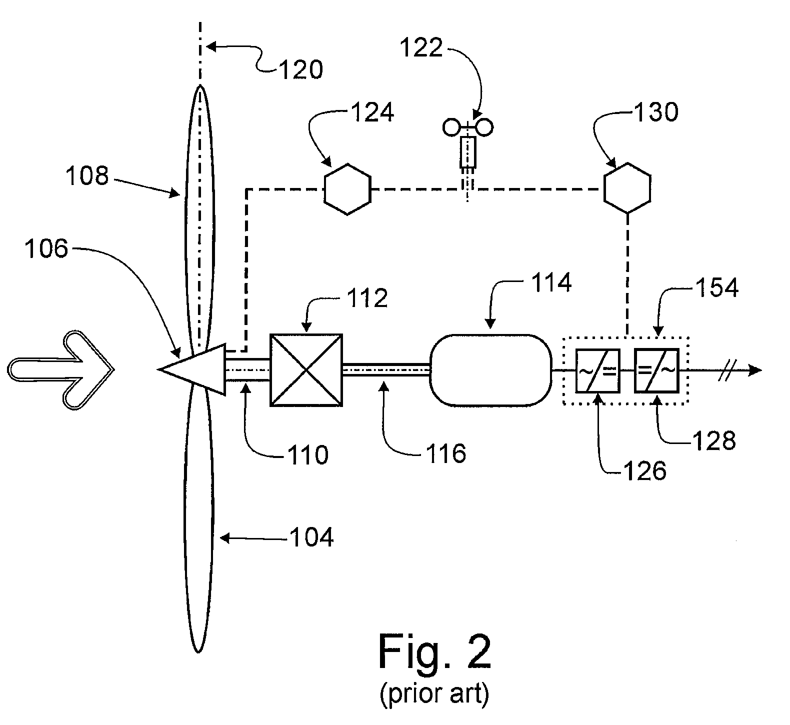
[0033]FIG. 2 shows the power train for a prior art variable speed wind turbine. As with constant speed turbines, the rotor 104 includes a hub 106 and a plurality of blades 108 each having an a...


PUM


Abstract

A variable speed wind turbine including a variable speed rotor, a large constant speed generator, and a small variable speed generator is characterized by a three-shaft variable ratio gearbox connecting the shaft of the rotor with the two generator shafts. The variable ratio gearbox is an epicyclic gearbox which enables the combination of the high performance of a variable speed rotor with the low cost of a large constant speed generator. The torque of the small variable speed generator controls the rotor speed. Variable frequency power conditioning cost is less than that of a prior art variable speed wind turbine, reduced by the ratio of the rated capacity of the small generator to total rated capacity. Also, the small generator enables efficient low wind velocity energy capture. The low rotational inertia of the small variable speed generator further reduces drive train dynamic stress.

Description

BACKGROUND OF THE INVENTION[0001]The present invention relates to an improved horizontal axis wind turbine for generating alternating current electricity which can be supplied to an electrical power grid.[0002]Wind turbines can be broadly classified as either constant speed or variable speed. Each category has its own strengths and weaknesses. The present invention utilizes a three-shaft variable ratio gearbox to exploit the advantages of a variable speed rotor yet retains the lower cost of a constant speed generator producing most of the output power.BRIEF DESCRIPTION OF PRIOR ART[0003]A typical megawatt sized constant speed wind turbine operates at 20 rpm rotor speed and includes a fixed speed generator driven by the rotor via a fixed ratio gearbox. Typical generators are two poles, 60 Hz, 1800 rpm. The gearbox has a 90:1 fixed ratio. This is typically accomplished in several stages with fixed ratio planetary gears.[0004]As wind velocity increases from zero, the rotor begins to tu...

Claims


Application Information

Patent Timeline
16 Sep 2010
Publication
US20100230966A1
IPC
H02P9/04
CPC
F03D9/002; F03D11/02; Y02E10/725; Y02E10/722; F05B2260/40311; F03D9/25; F03D15/00; F03D15/10
Inventors
PAVLAK, ALEXANDER J.