
Variable Speed Wind Turbine With Doubly-Fed Induction Generator Compensated For Varying Rotor Speed

a variable speed wind turbine and variable speed technology, applied in the direction of motors, engine control, position/direction control, etc., can solve the problems of increasing the complexity of the electrical system of a modern wind turbine, the speed range of the system, and the requirement for ac-ac converters to handle the full output power of the turbine, so as to reduce the oscillations and reduce the instability of the control system.

Active Publication Date: 2010-02-25
VESTAS WIND SYST AS
View PDF10 Cites 28 Cited by
  • Summary
  • Abstract
  • Description
  • Claims
  • Application Information

AI Technical Summary

Benefits of technology

[0029]This is advantageous in that the rotor current controller will work on the resulting generator transfer function of the compensated generator system and, thus, compensation means are not needed within the controller.
[0037]Arranging the compensation means transfer function to provide a control output that effectuates a decoupling of the rotor currents into two mutually orthogonal components is advantageous in that it enables the currents to be controlled individually by the rotor current controller, so that a more precise control of the rotor currents and thereby of the stator currents and the power delivered to the network may be obtained. A complete or at least nearly complete decoupling of the current components may be obtained due to the provision of the rotor angle speed independency.
[0040]Using lead filters for increasing the phase of the output control signal from the compensation means around the potential oscillation frequency is advantageous in that it minimizes the oscillations around this frequency and, thus, the instability of the control system considerably.

Problems solved by technology

Also, newer grid requirements add to the complexity of the electrical systems of a modern wind turbine.
A disadvantage, on the other hand, is that the AC-AC converter must be rated to handle the full output power of the turbine.
The limitations on the speed range of the system depend on the AC-AC converter, since the amount of power through the rotor is proportional to the difference between the electrical rotor speed and the synchronous speed (stator field speed) of the generator.
The DFIG system suffers from a well-known disadvantage, namely poorly damping of oscillations within the flux dynamics due to cross coupling between active and reactive currents, which makes the system potentially unstable under certain circumstances and complicates the work of the rotor current controller, whose main task is to limit the rotor current in order to prevent the AC-AC converter from tripping or breaking down.
Furthermore, the controller performance (bandwidth, rise time etc.) depends on the rotor speed, which in best case results in high qualification and test costs and in worst case can cause controller instability and hardware failure.
However, it is stated in the paper that the cross coupling between active and reactive power is of small influence and can be neglected, which is not in accordance with the common experience of most people working with modern wind turbines.
The methods mentioned all suffer from disadvantages, such as necessary differentiation of measured signals, reduction of rotor current controller bandwidth, need of extra inverter hardware etc.
This system, however, does not provide any solution to the above-mentioned problem of potential instability of the system due to oscillations in the flux dynamics.

Method used


Image

  • Variable Speed Wind Turbine With Doubly-Fed Induction Generator Compensated For Varying Rotor Speed
  • Variable Speed Wind Turbine With Doubly-Fed Induction Generator Compensated For Varying Rotor Speed
  • Variable Speed Wind Turbine With Doubly-Fed Induction Generator Compensated For Varying Rotor Speed

Examples


Embodiment Construction

[0065]In the following is disclosed an embodiment of the present invention with compensation means for making the generator transfer function independent of varying rotor speed, comprising a lead filter for damping oscillations around the grid frequency.

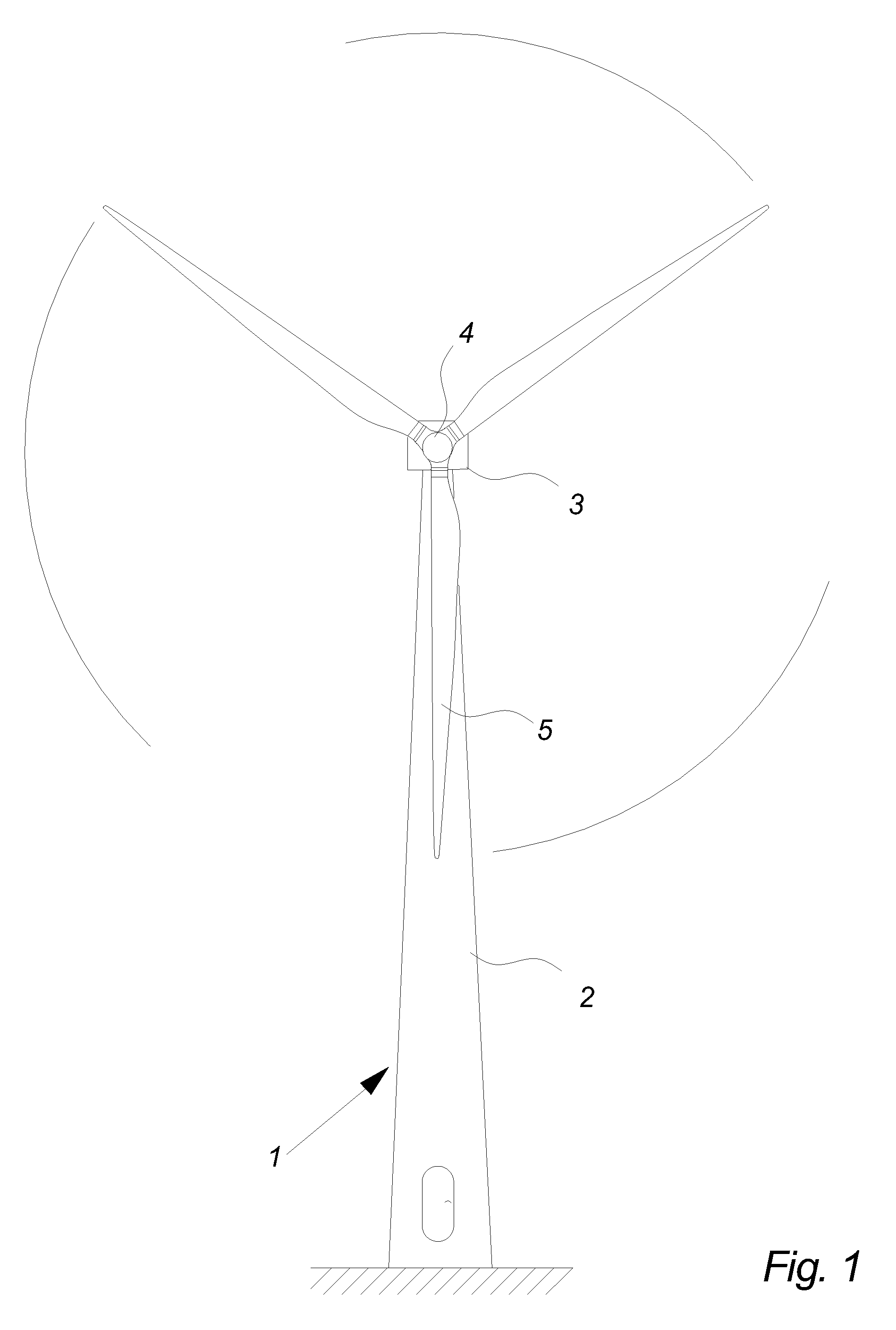
[0066]FIG. 1 illustrates a modern wind turbine 1, comprising a tower 2 and a wind turbine nacelle 3 positioned on top of the tower 2. The wind turbine rotor 4 comprising three wind turbine blades 5 is connected to the nacelle 3 through the low speed shaft (not shown) which extends from the front of the nacelle 3.

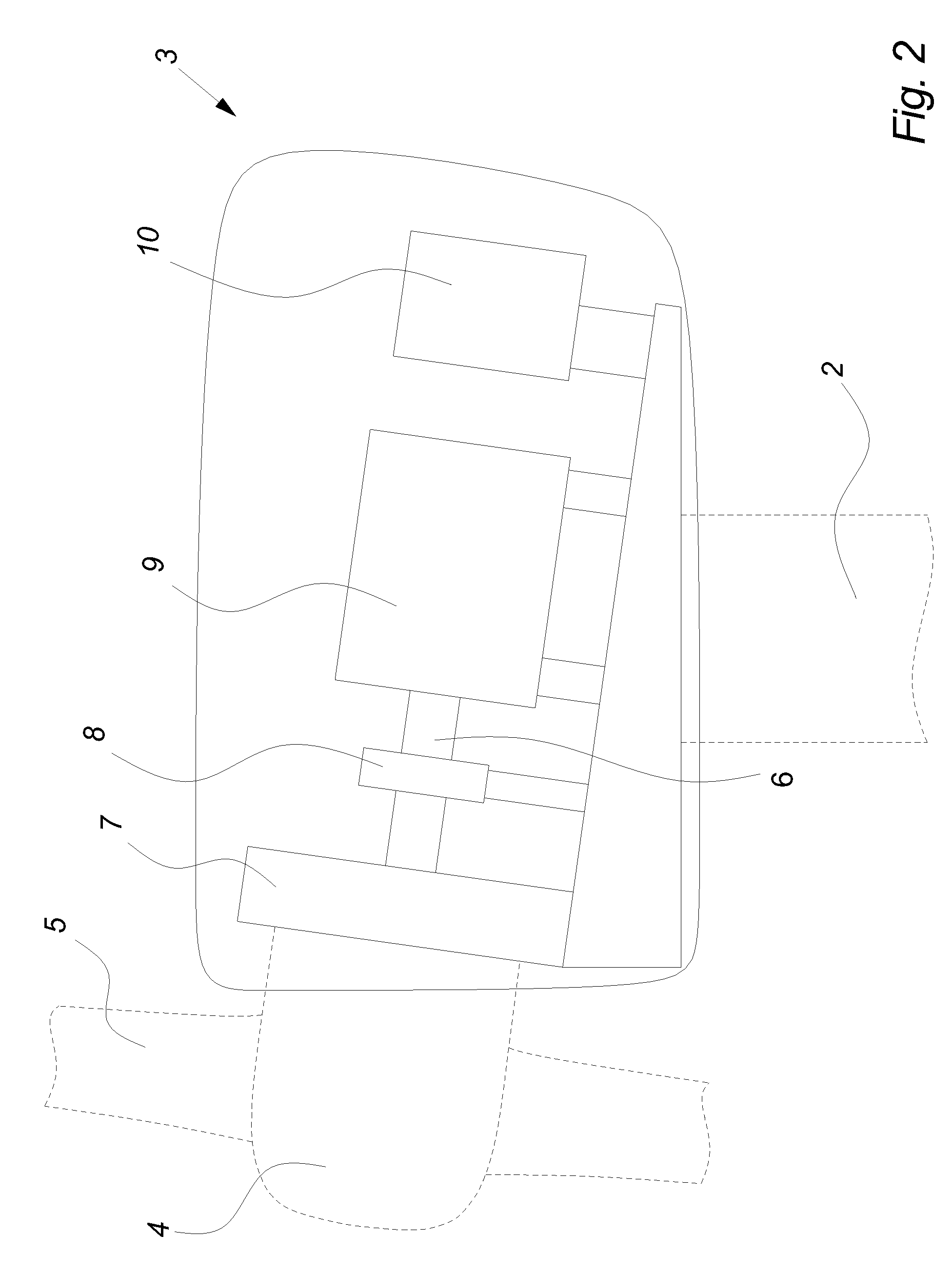
[0067]FIG. 2 illustrates a simplified cross section of a wind turbine nacelle 3, as seen from the side. In the shown embodiment, the drive train 6 in the nacelle 3 comprises a gear 7, a breaking system 8, a generator 9 and an AC-AC converter 10.

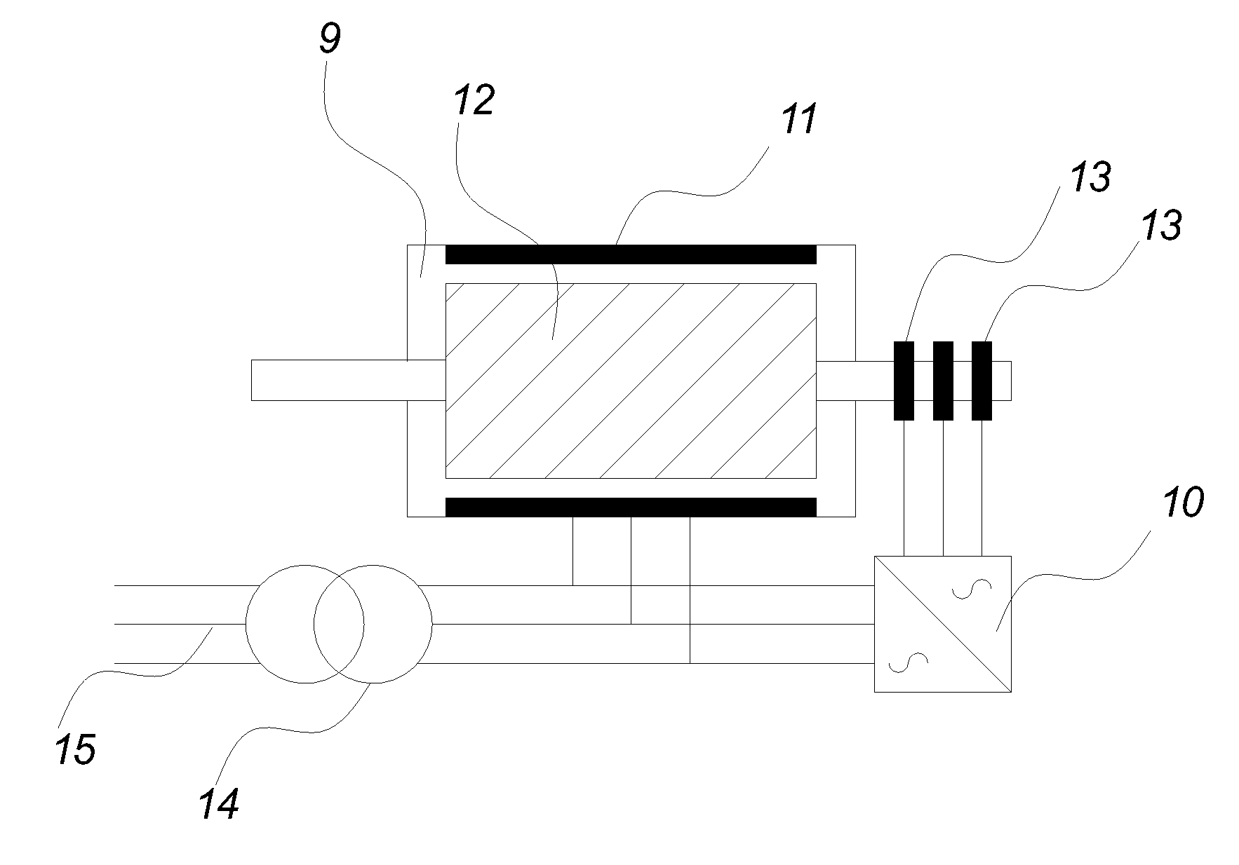
[0068]The principle schematics of a standard Doubly-Fed Induction Generator 9 is illustrated in FIG. 3, where the stator 11 is connected to the grid 15 via a grid transformer 14 and th...


PUM


Abstract

A variable rotational speed wind turbine includes a doubly-fed induction generator, a rotor current controller for controlling the rotor currents of the generator, a compensation mechanism having a computation mechanism, and an input mechanism for providing input to the compensation mechanism, the input being representative of at least the instantaneous angular speed of the rotor of the generator. The computation mechanism is arranged to compute an instantaneous compensation control output in dependency of the instantaneous angular speed of the rotor of the generator and feed the compensation control output to the rotor, and to compute the compensation control output during operation of the wind turbine to compensate at least partly for dependencies on the rotor angular speed of the locations of poles of a generator transfer function, thus making a resulting generator transfer function substantially independent of variations in the rotor angular speed during operation of the wind turbine.

Description

CROSS-REFERENCE TO RELATED APPLICATIONS[0001]The present application is a continuation of pending International patent application PCT / DK2008 / 000168 filed on Apr. 30, 2008 which designates the United States and claims priority from U.S. Provisional Patent Application Ser. No. 60 / 915,836 filed on May 3, 2007 and Danish patent application PA 200700654 filed on Apr. 30, 2007, the content of which is incorporated herein by reference.FIELD OF THE INVENTION[0002]The present invention relates to a variable speed wind turbine comprising a doubly-fed induction generator and a method for compensating the generator for varying rotor speed.BACKGROUND OF THE INVENTION[0003]Generally, commercial wind turbines can be divided into fixed speed turbines and variable speed turbines.[0004]For a fixed speed turbine, the power production is only optimized for one specific wind speed, whereas for a variable speed turbine, optimal power output can be achieved for a wider range of wind speeds.[0005]Since th...

Claims


Application Information

Patent Timeline
IPC IPC(8): H02P9/04H02P9/42G06F19/00
CPCF03D7/0272F03D9/003Y02E10/723F05B2270/327F05B2270/104F03D9/255Y02E10/72
Inventor BENDIXEN, FLEMMING BUUSANDERSEN, GERT KARMISHOLTLARSEN, KIM BRONDUM
Owner VESTAS WIND SYST AS
Learn More