Variable speed wind turbine with a doubly-fed induction generator and rotor and grid inverters that use scalar controls

a variable speed, generator technology, applied in the direction of engine control, motors, optimising machine performance, etc., can solve the problems of increasing rotor heating, overexcitation of generators, and underexcitation of generators, so as to improve the effect of low voltage faults and precise control of individual stators

Inactive Publication Date: 2012-06-12
VESTAS WIND SYST AS
View PDF8 Cites 39 Cited by
  • Summary
  • Abstract
  • Description
  • Claims
  • Application Information

AI Technical Summary

Benefits of technology

[0035]As well, graduated protection of the DC link and associated inverters components is provided. The output inverters thus continuously load the DC link even though a fault is occurring, while DC Choppers across the link and a Crowbar across the rotor are available to reduce the effects of a low voltage fault, helping keep the wind turbine connected and providing power to the grid. To ensure operation of the grid inverter and other subsystems at very low fault voltages a UPS is used to supply the auxiliary power to the subsystems, during normal and fault situations.

Problems solved by technology

When excess current is applied to the rotor, the generator is considered to be overexcited.
If the generator receives too little rotor current, it is considered to be underexcited.
Rotor heating is also due to rotor core losses from excitation flux.
Any increases in rotor current to increase reactive power generation therefore increases rotor heating.
In doubly fed induction generators, there are therefore power output limits mandated by heating considerations.
Although absorption of reactive power does not increase rotor heating above what would be experienced by delivery of only real power, the increase in flux due to absorption of reactive power causes excess heating of end sections of a generator's stator.
Therefore, there are also power output limits of DFIG systems due to stator end heating.
However, with FOC, otherwise useful information regarding the AC current in each phase is lost in the transformation process.
Because in certain instances the AC signals are asymmetrical (that is, not equal), useful AC information may be lost during the transformation of AC signals from the stationary frame into a rotating frame.
As a consequence, FOC is unable to be used in a system that independently controls the electrical quantities (e.g., voltage, current) of each phase of the power grid.
However, the electrical quantities on each phase of a wind turbine generator may vary due to transients on the grid which may cause uneven thermal stress, unbalanced mechanical forces and high DC link voltages.
Staying connected during fault conditions can have adverse consequences to mechanical components as well.
If power load on a wind turbine is reduced, as it is in a low voltage fault condition, the blades of the turbine could accelerate and damage may occur.
Stated differently, as the wind speed increases, the rotational speed of the generator increases and brings it closer to the upper speed limit of the rotor and generator, and therefore it is not possible to operate a wind turbine at its optimum blade tip-wind speed ratio over the whole wind speed range.

Method used


Image

  • Variable speed wind turbine with a doubly-fed induction generator and rotor and grid inverters that use scalar controls
  • Variable speed wind turbine with a doubly-fed induction generator and rotor and grid inverters that use scalar controls
  • Variable speed wind turbine with a doubly-fed induction generator and rotor and grid inverters that use scalar controls

Examples


Embodiment Construction

[0049]Reference will now be made in detail to embodiments of the invention, examples of which are illustrated in the accompanying drawings. Wherever possible, the same reference numbers will be used throughout the drawings to refer to the same or like parts.

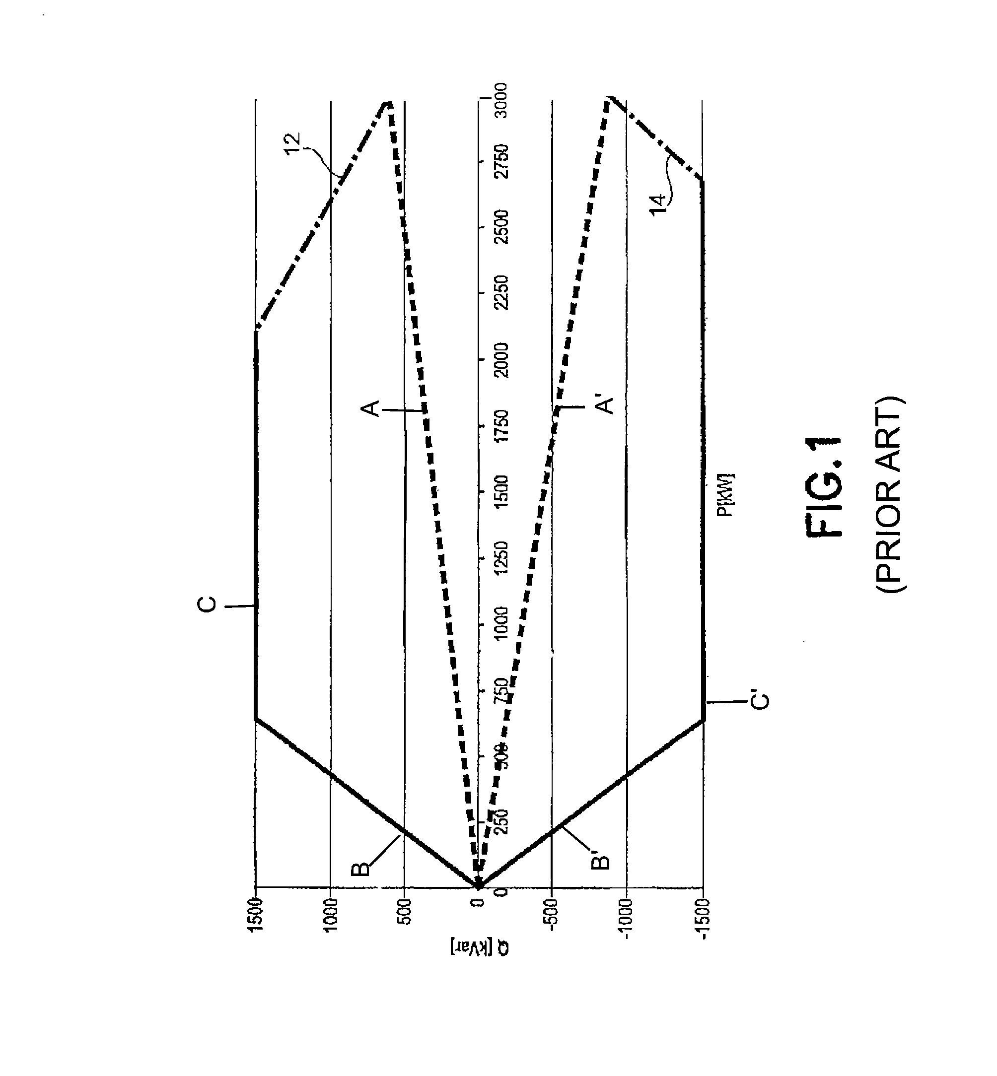
[0050]FIG. 1 describes power output limits of a known DFIG, with line 12 showing the output limits due to rotor heating and line 14 showing output limits due to stator end heating. That is, in order to produce more reactive power (Q) when the reactive power corresponds to a power factor of 0.98 (labeled as Line A) due to thermal limits of the generator rotor circuit (shown by Lines B and C) and when the DFIG is operating at full power (i.e., 3000 kW) the active power (P) must be limited as shown by line 12. Similarly, to absorb more reactive power when the thermal limit of the stator (shown by Lines B′ and C′) is defined by a power factor of 0.96 (labeled as Line A′), the active power must be reduced as shown by line 14.

[0051]FIG...


PUM


Abstract

The present invention relates to an improved wind turbine, of the type which employs doubly fed induction generators (DFIG), and a wind park including the same, which permits the use of lighter weight turbines, with the ability to have greater energy capture, more precise control of asymmetrical phases and enhanced maintenance and support of the grid during fault conditions.

Description

BACKGROUND OF THE INVENTION[0001]1. Field of the Invention[0002]The present invention relates to an improved wind turbine, of the type which employs doubly fed induction generators (DFIG), and a wind park including the same, which permits the use of lighter weight turbines, with the ability to have greater energy capture, more precise control of asymmetrical phases and enhanced maintenance and support of the grid during fault conditions.[0003]Specifically, the present invention relates to wind turbines configured for operation either singly, in small concentrations, or in wind parks, each turbine being a variable speed turbine using a doubly fed induction generator (DFIG) with grid side inverters, having power provided from both their generator stators and rotors, and preferably with major contributions of reactive power for grid voltage support being provided by park level static reactive power sources. As well, the present invention contemplates the use of blade pitch control, whi...

Claims


Application Information

Patent Timeline
Patent Type & Authority Patents(United States)
IPC IPC(8): H02P9/04F03D9/00
CPCF03D7/0224F03D7/0272F03D7/0276F03D7/044F03D9/005H02P9/007H02P9/04H02P9/102H02P2101/15F05B2270/20Y02E10/723F05B2270/1033F03D9/257Y02E10/72F03D7/02
Inventor JORGENSEN, ALLAN HOLMHELLE, LARSSCHAIER, LEONARD
Owner VESTAS WIND SYST AS
Why Eureka
Try Eureka