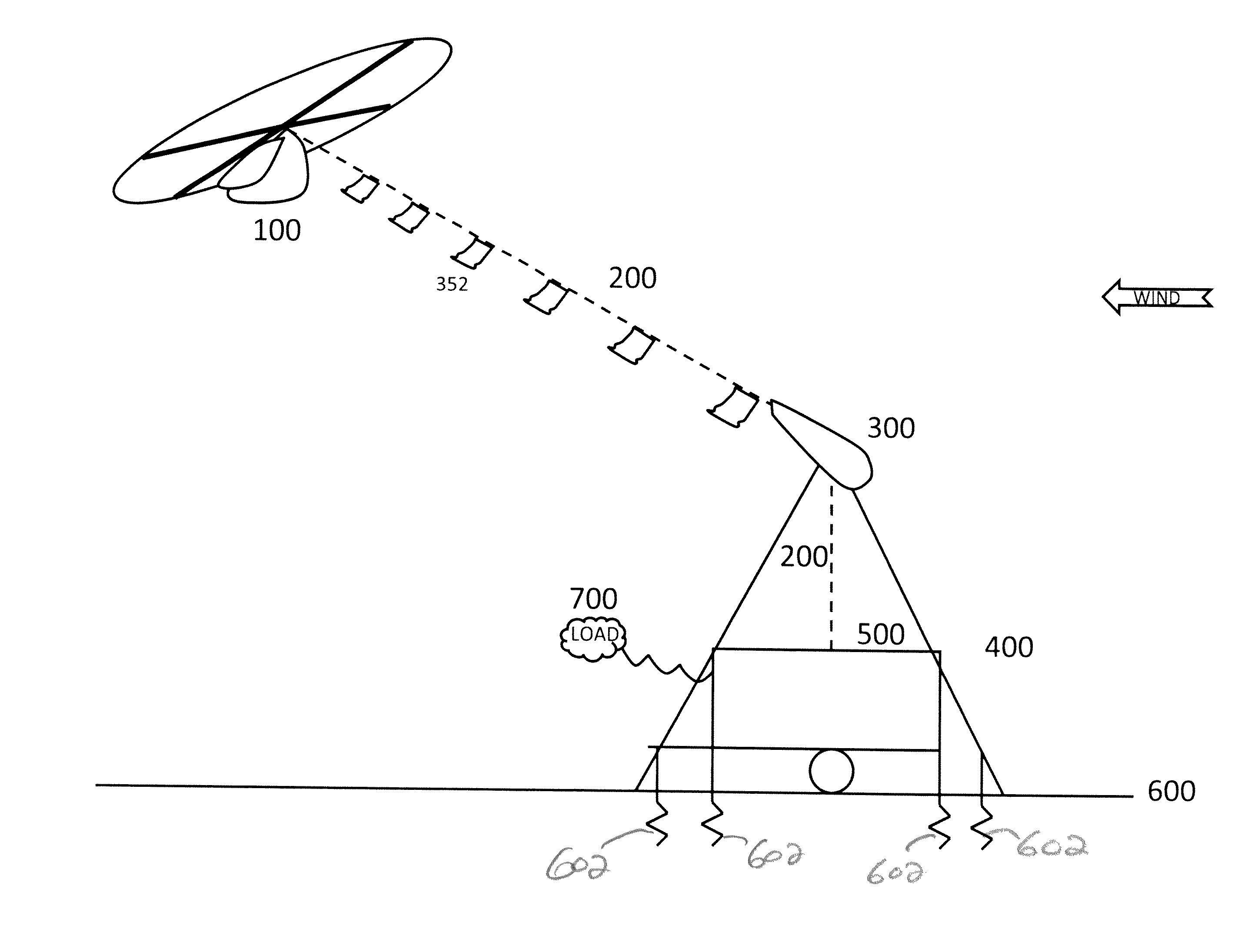
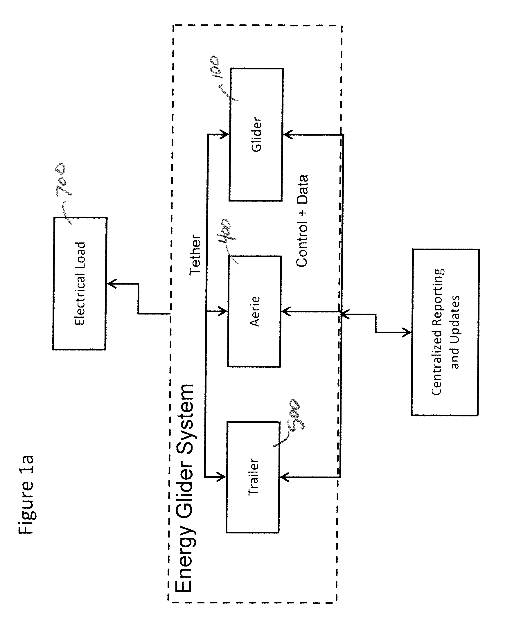
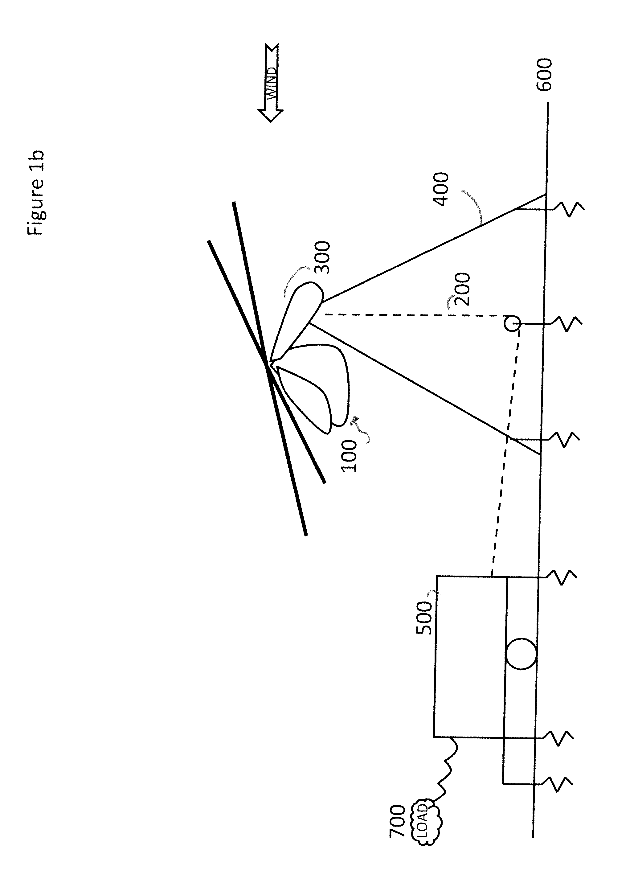
“Ground-Gen” systems keep the generator on the ground and generally use the flying vehicle to pull the tether resulting in a
spinning force being applied to the generator
system on the ground.
However, no AWECS has ever become a commercially available product, primarily for technological reasons.
Generally, prior art systems suffered from two primary technological disadvantages that made the most practical AWECS designs commercially infeasible.
More specifically, the strength to weight ratios of tethers and the cost to
performance ratio of
automation systems were both woefully inadequate.
Twenty years ago, before the advent of extremely high strength to weight ratio synthetic fibers, AWECS with commercial levels of energy production simply were not possible.
Steel cable would have been one of a few reasonably priced materials strong enough but disadvantaged if its weight would be more than a hundred pounds per thousand feet.
That tether weight added to any flying vehicle's required lift made AWECS impractical.
Additionally, steel cable utilized in a ground-gen
system—likely performing more than a thousand power strokes every day and close to a million every year—would suffer extreme wear and need perhaps monthly replacement, an added maintenance cost making the system impractical to operate.
Additionally,
automation systems and components, such as sensors, servos, and controllers were not developed or included in any meaningful way that met AWECS
automation requirements, especially for ground-gen systems, to maintain system flight in the face of changing weather conditions, or to optimize power-
stroke cycle of tether pulling and retraction, potentially thousands of times a day.
In prior art AWECS, automated control systems did not facilitate commercial feasibility.
No systems were known or implemented to allow the system to operate continuously, unattended by humans for weeks and months at a stretch.
Generally, AWECS development has been limited to research projects only.
More recently, some of the AWECS known in the art may have some merit as commercially viable systems, but they still lack
system requirements necessary for commercial success.
In particular known systems still lack launch and landing methods to get the flying vehicle into the air and back on the ground, automatically, reliably and repeatedly, with no human assistance.
No prior art for AWECS clearly defines this problematic part of the system.
Yet even in the most ideal locations, some hours of every month will see winds drop below the speeds necessary to maintain
unpowered flight.
No known ground-gen AWEC systems define a method of maintaining flight in zero-speed winds aloft nor any control systems to control those flying vehicles to descend and land in such low-wind conditions.
Similarly, no landing facility has been described in the prior art, nor any
automated method of re-launching when wind conditions improve.
However, all prior art then describes systems made of fabrics proven by the ultralight
aircraft industry to survive only a few thousand hours of
exposure before becoming dangerously weakened.
The prior art does not address
longevity—the ability of the system to operate for many years with minimal down-time and replacement costs.
These composites increase material costs high enough that the system purchase price then requires more than a decade of payback period—un-sellable in the
renewable energy market.
Alternatively, the prior art describes fabrics, as noted above, requiring replacement after only a few months of operation, thus increasing maintenance costs beyond commercially feasible levels.
Similarly, high-friction
capstan ground-gen systems may require tether replacements every few days, weeks or months, again inducing maintenance and replacement costs making the system commercially infeasible.
The prior art does not disclose or suggest broad flight envelopes—the ability for the system to maintain flight and energy production in the face of a broad range of wind and weather conditions.
However, tethered flight involves an entirely different set of stability algorithms.
Yet no prior art describes a flying vehicle able to cost-effectively maintain that broad a
flight envelope.
However, the requirement for making the moored object's tether visible to
aircraft pilots is not likely to be dropped.
Tethers on ground-gen AWECS are particularly problematic—experiencing more than a
ton of load while extending and retracting possibly hundreds of feet with each
power stroke.
Flags directly mounted to the tether risk gumming up the works at the ground generation system.
Further, the high-strength tether lines AWECS require are particularly slippery.
For ground-gen AWECS utilizing a
capstan to capture the torque and motion of the tether, friction between the tether and the capstan is critical, but also damaging.
This coil to coil contact and resulting friction prematurely wears the tether, fraying and weakening it quickly enough to require replacement too frequently for commercial viability.
The prior art makes no mention of, nor offers any solutions to the problems introduced by high-strength but slippery tether lines.

