
Inflatable shaping system reducing the aerodynamic drag upon the rear of a vehicle

a technology of aerodynamic drag and shaping system, which is applied in the direction of roofs, transportation and packaging, vehicle arrangements, etc., can solve the problems of affecting the opening and closing of the trailer, few hoods and foils have seen use on the rear of the trailer or truck, etc., and achieves simple and convenient stowage method, low manufacturing cost, and reduced volume

Inactive Publication Date: 2010-09-16
MRACEK MILO F
View PDF15 Cites 9 Cited by
  • Summary
  • Abstract
  • Description
  • Claims
  • Application Information

AI Technical Summary

Benefits of technology

[0010]The use of multiple inflatable elements with the overlaid skin minimizes large stress loads endured by the structural frame. The internal pressure loads are reacted by hoop tension within the inflatable member, not by bearing upon the structure of the rigid frame. The frame endures the bearing loads, imparted to the overlaid skin, where attached to the frame around its perimeter where most structurally efficient. This position of the inflatable elements together with the controlled load paths leads to significant overall weight reduction of the present invention. Saving weight minimizes the additional dead load added to the tractor trailer weight thus reducing the adverse effects of deploying this invention upon a trailer. The present invention at its low weight improves the fuel efficiency and tonnage per mile of a trailer or enclosed cargo truck.
[0019]Another object the inflatable shaping system is to provide such a system that has a low cost of manufacturing so the purchasing organizations can readily purchase it through stores and supply sources.

Problems solved by technology

However, few hoods and foils have seen use on the rear of a trailer or truck.
Placing a permanent hood upon the rear of a trailer interferes with opening and closing the trailer during cargo handling.

Method used


Image

  • Inflatable shaping system reducing the aerodynamic drag upon the rear of a vehicle
  • Inflatable shaping system reducing the aerodynamic drag upon the rear of a vehicle
  • Inflatable shaping system reducing the aerodynamic drag upon the rear of a vehicle

Examples


Embodiment Construction

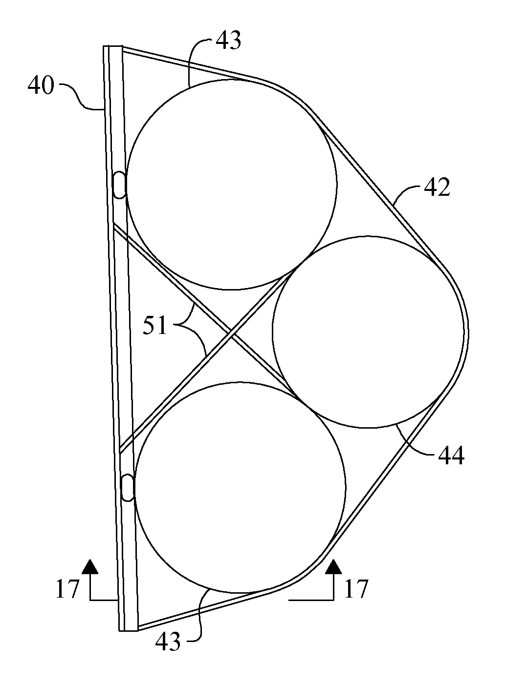
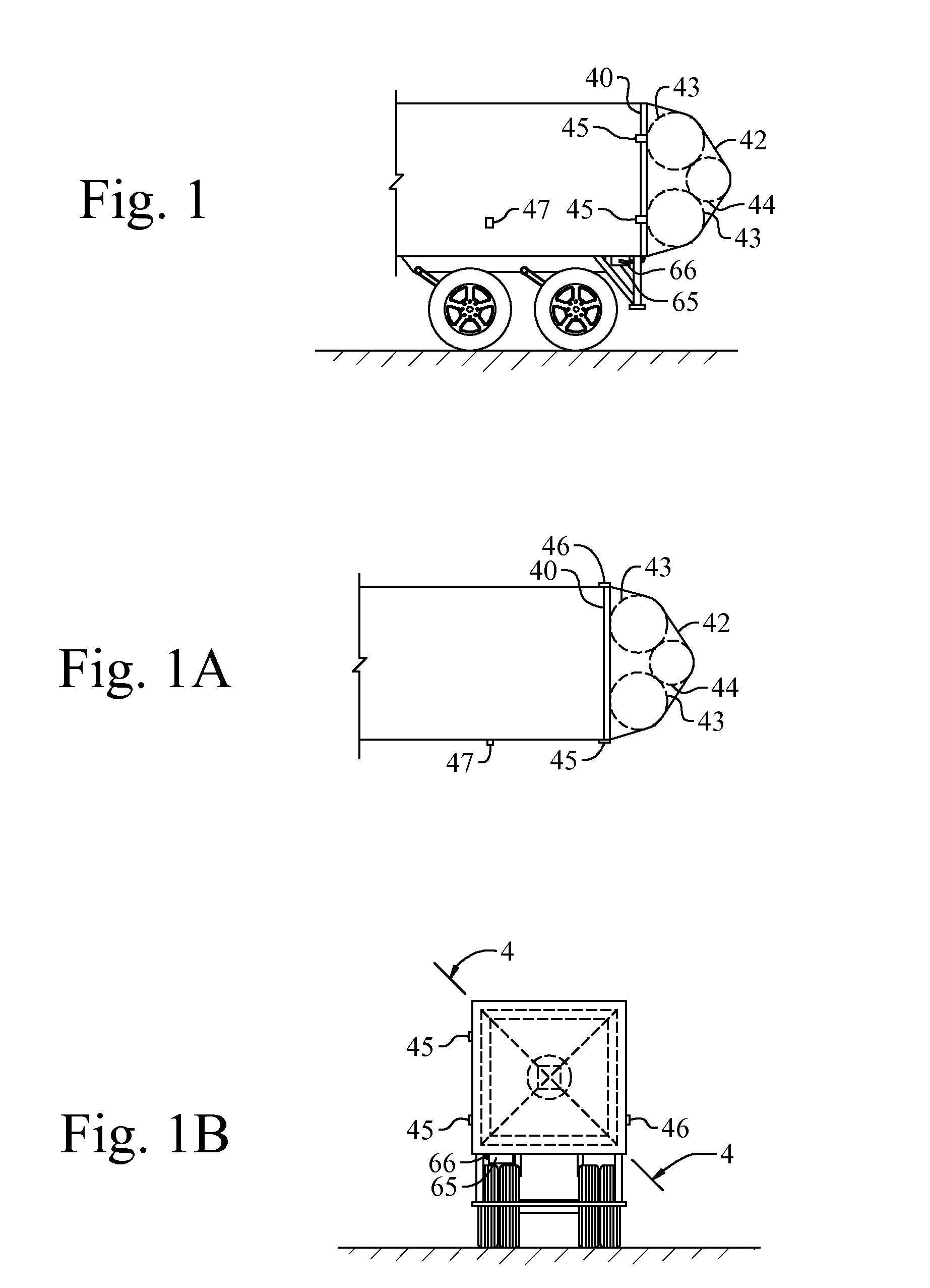
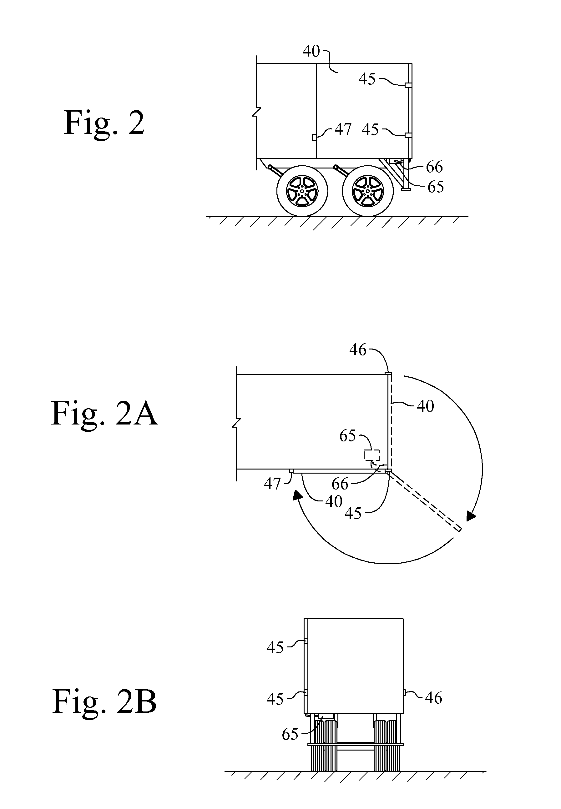
[0041]The present art overcomes the prior art limitations by providing a inflatable shaping system, as in FIG. 1 that overcomes the limitations of prior is devices and methods for reducing drag upon the rear of trailers or self propelled vans or trucks with cargo boxes. Referring to FIGS. 1-18:

[0042]40 generally denotes a structural rigid frame assembly for the preferred embodiment of the present invention.

[0043]42 is an externally tensioned cover skin, or flexible member, that forms the deployed aerodynamic after body shape.

[0044]43 denotes the base inflatable element, or major element, of this preferred embodiment. It has a shape formed of four intersecting cylinders having mitered corners that form a square shape in plan view, later shown in FIG. 18. The inflatable element is made of strong, flexible, leak proof material, such as nylon and the like.

[0045]44 is a second inflatable element, or minor element, spherical in shape when inflated. Elements 43, 44 are flexibly bonded to o...


PUM


Abstract

An inflatable shaping system has a frame, rectangular with four sides, similar to the rear of a trailer or truck. The frame has a hinged connection and swings from an over-the-road configuration and to a deflated stowed position against the side of the trailer. Upon the frame, the system has an inflatable body and a durable skin covering the frame and the inflatable body. The inflatable body has a continuous attachment to the frame. The inflatable body has at least one inflatable element connected by a flexible adhesive or device. The inflatable elements remain contained between the frame and the durable skin, generally outwardly from the trailer. In communication with the inflatable elements, a pump system supplies air for their inflation and removes air for their deflation. The pump system operates remotely in the vicinity of the truck.

Description

CROSS REFERENCE TO RELATED APPLICATION[0001]This non-provisional application claims priority to the pending provisional application Ser. No. 61 / 209,913 filed Mar. 13, 2009 which is commonly owned by the same inventor.BACKGROUND OF THE INVENTION[0002]The inflatable shaping system reducing the aerodynamic drag upon the rear of a vehicle generally relates to drag reduction devices and more specifically to an inflatable and deflatable device that alters the shape of the rear of a trailer or truck. The present invention reduces the aerodynamic drag caused by the blunt rear ends of over-the-road semi trucks and trailers. The present invention utilizes inflatable members that stretch a covering upon the rear of a trailer which alters the shape of the trailer encountered by air flow during motion. The altered shape of the trailer lessens drag and improves fuel mileage for is trailers and trucks.[0003]Various goods, commodities, and equipment move around the country by truck. Trucking moves ...

Claims


Application Information

Patent Timeline
Patent Type & Authority Applications(United States)
IPC IPC(8): B62D37/02
CPCB62D35/004
Inventor MRACEK, MILO F.
Owner MRACEK MILO F
Learn More