Disk drive device for rotating a disk

Inactive Publication Date: 2010-09-16
SAMSUNG ELECTRO MECHANICS JAPAN ADVANCED TECHNOLOGY CO LTD
View PDF8 Cites 21 Cited by
  • Summary
  • Abstract
  • Description
  • Claims
  • Application Information

AI Technical Summary

Benefits of technology

[0011]The present invention addresses these disadvantages, and a general purpose of one embodiment of the present invention is to

Problems solved by technology

However, if, for example, a leak occurs at a drawing-out hole for a wire of a coil arranged on the base plate, particles outside may enter in the regi

Method used


Image

  • Disk drive device for rotating a disk
  • Disk drive device for rotating a disk
  • Disk drive device for rotating a disk

Examples


Example

The First Embodiment

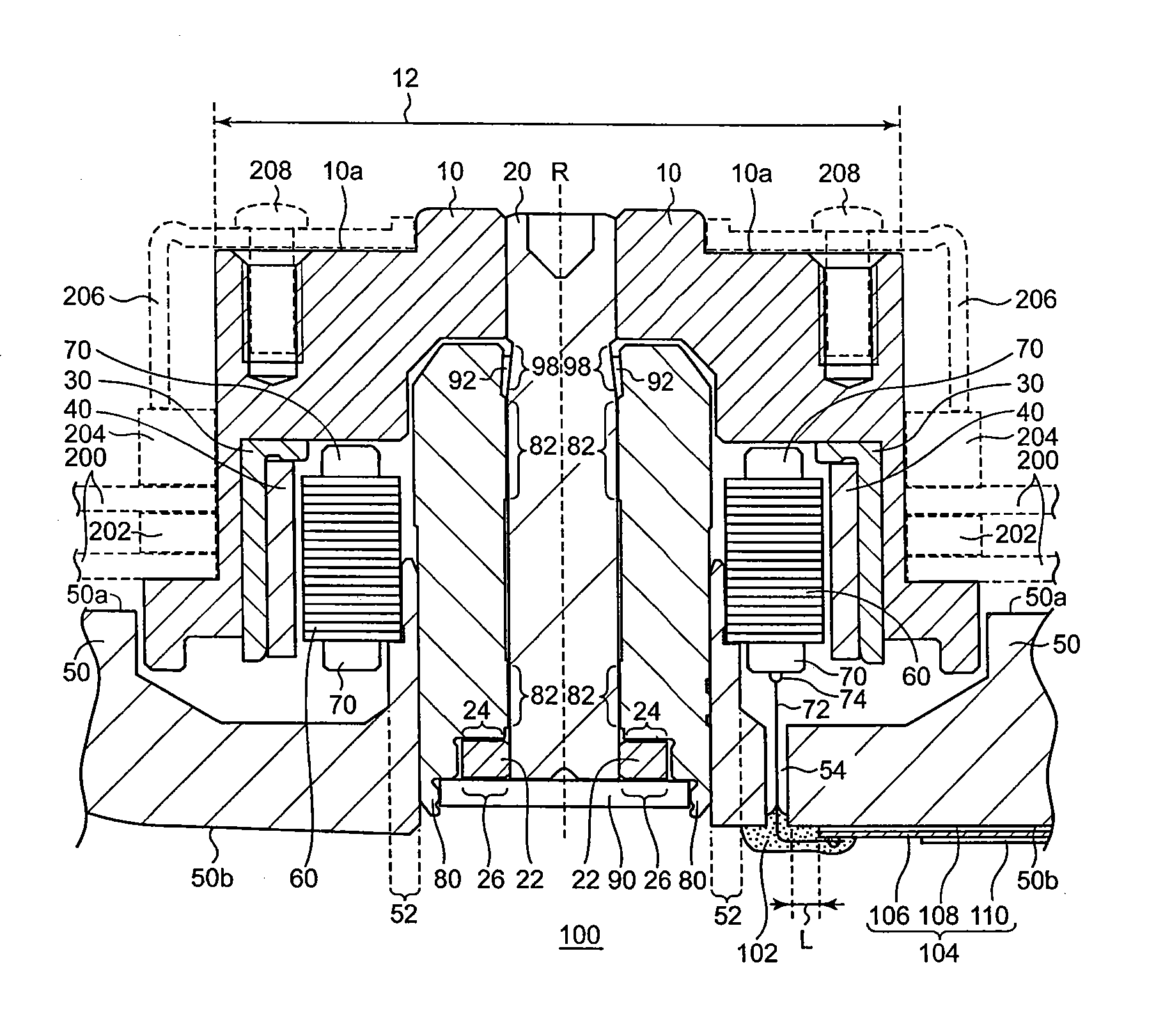
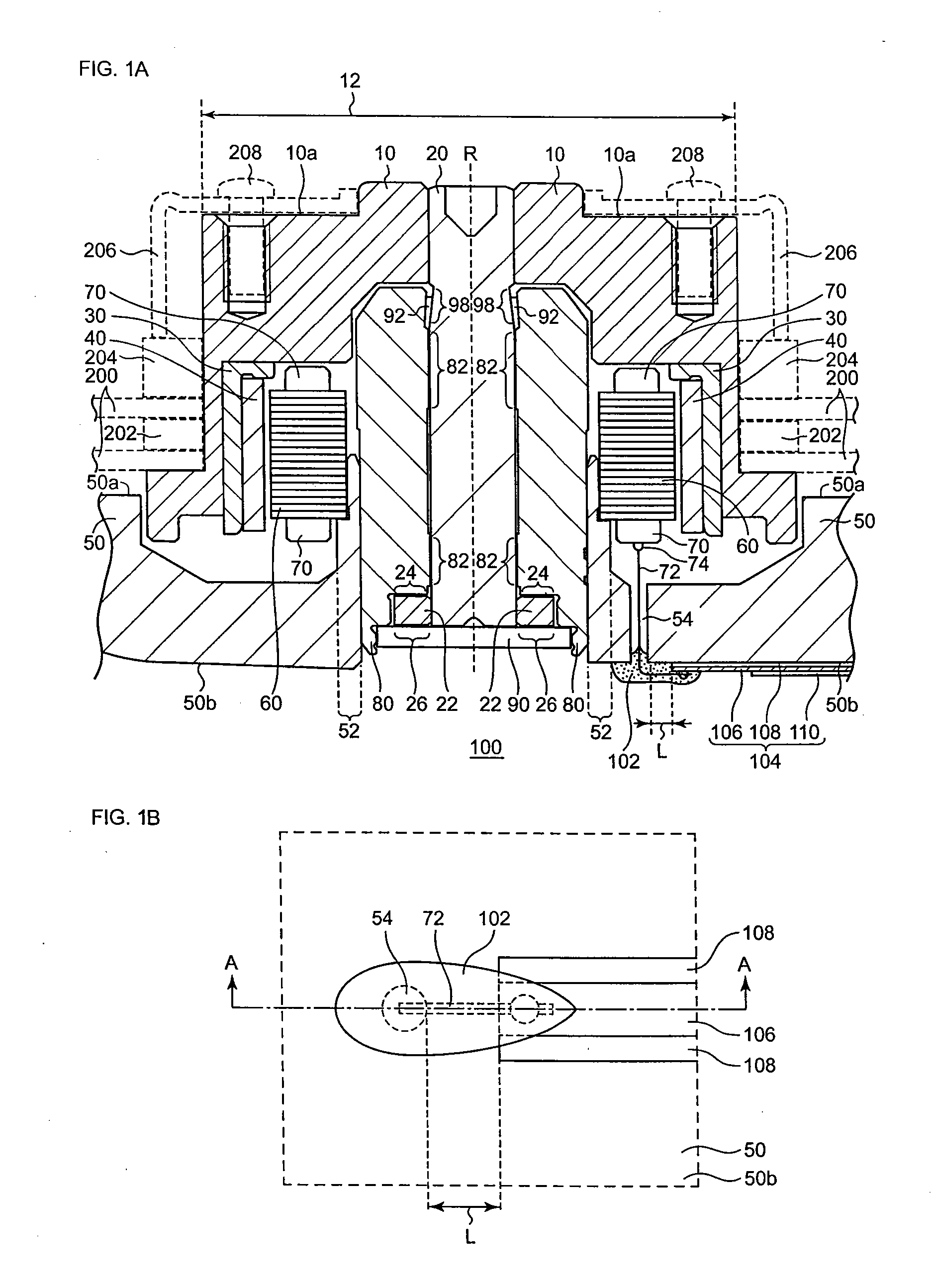
[0031]In the brushless motor 100 according to the first embodiment of the present invention, a wire 72 of one end of a coil 70 is drawn out to a bottom surface 50b of a base plate 50 through a hole 54 arranged on the base plate 50. The wire 72 of said end of the coil 70 is connected to a driving line or driving wiring 106 at a position other than the position of or on or above the hole 54. Further, in the brushless motor 100, the hole 54 is plugged with a resin 102 in order to keep it airtight. As a result, electrically connecting the driving line 106 and the wire 72 can be performed independently from sealing the hole 54 of the base plate 50, thereby the reliability of each act can be increased.

[0032]FIG. 1A is a cross-sectional view of the brushless motor 100 according to the first embodiment of the present invention. FIG. 1B is a partial bottom view of the brushless motor 100 according to the first embodiment of the present invention. FIG. 1B is a bottom view ...

Example

The Second Embodiment

[0064]The main difference between the brushless motor 400 according to the second embodiment and the brushless motor 100 according to the first embodiment resides in the shape of the insulation film.

[0065]FIG. 3A is a partial cross-sectional view of the brushless motor 400 according to the second embodiment. FIG. 3B is a partial bottom view of the brushless motor 400 according to the second embodiment. FIG. 3A is a partial cross-sectional view of the brushless motor 400 near the hole 54 arranged on the base plate 50. FIG. 3B is a bottom view near the hole 54 of the base plate 50. FIG. 3A is the view that is sectioned along the line C-C, as illustrated in FIG. 3B.

[0066]The description will be omitted with regard to the portion(s) of the brushless motor 400 that is / are not shown in FIG. 3A or FIG. 3B since the portion(s) has / have a structure similar to that / those of the brushless motor 100 according to the first embodiment of the present invention.

[0067]The insula...

Example

The Third Embodiment

[0072]The main difference between the brushless motor 500 according to the third embodiment and the brushless motor 100 according to the first embodiment resides in the shape of the insulation film.

[0073]FIG. 4A is a partial cross-sectional view of the brushless motor 500 according to the third embodiment. FIG. 4B is a partial bottom view of the brushless motor 500 according to the third embodiment. FIG. 4A is a partial cross-sectional view of the brushless motor 500 near the hole 54 arranged on the base plate 50. FIG. 4B is a bottom view near the hole 54 of the base plate 50. FIG. 4A is the view that is sectioned along the line D-D, as illustrated in FIG. 4B.

[0074]The description will be omitted with regard to the portion(s) of the brushless motor 500 that is / are not shown in FIG. 4A or FIG. 4B since the portion(s) has / have a structure similar to that / those of the brushless motor 100 according to the first embodiment of the present invention.

[0075]With regard to...


PUM


Abstract

In the brushless motor, a magnetic recording disk is to be mounted on a hub. A base plate rotatably supports the hub on the upper surface. A laminated core is fixed on the upper surface of the base plate and has a ring portion and a plurality of teeth that extend radially from the ring portion. Coils are wound around the plurality of teeth. A cylindrical magnet is fixed to the hub and is magnetized for driving with a plurality of poles along the circumferential direction and is arranged to radially face the plurality of teeth of the laminated core. A wire of one end of one of the coils is drawn out to the bottom surface of the base plate through a hole arranged on the base plate. The wire is connected to a driving line for supplying a current to the coils at a position other than the position of the hole on the base plate. The hole of the base plate is plugged with a resin.

Description

BACKGROUND OF THE INVENTION[0001]1. Field of the Invention[0002]The present invention relates to a disk drive device for rotating a disk.[0003]2. Description of the Related Art[0004]A hard disk drive is known as a medium used as a storage device in a computer. In a hard disk drive, a magnetic recording disk on which recording tracks are formed is rotated at high speed by a brushless motor disclosed in Japanese Patent Application Publication No. 2008-61331. A magnetic head is placed against the surface of the magnetic recording disk with a slight distance between them for the purpose of reading / writing magnetic data contained in the recording tracks.[0005]In recent years, Magneto-resistive elements (hereinafter referred to as “MR elements”) are widely used for magnetic heads since they are advantageous in terms of realizing a higher density. It is known that Thermal Asperity failure (hereinafter referred to as TA failure) may occur with regard to these MR elements.[0006]TA failure is...

Claims


Application Information

Patent Timeline
IPC IPC(8): H02K11/00
CPCH02K3/522H02K3/52H02K3/50H02K5/225G11B19/2036
Inventor YAMAZAKI, HIROKIMURAMATSU, HIROSHI
Owner SAMSUNG ELECTRO MECHANICS JAPAN ADVANCED TECHNOLOGY CO LTD
Why Eureka
Try Eureka