

Display Characteristic Feedback Loop
a feedback loop and display technology, applied in the field of color light sensors, can solve problems such as failure of one or more components, deformation of the display characteristic, and failure of reliable electronic displays
- Summary
- Abstract
- Description
- Claims
- Application Information
AI Technical Summary
Benefits of technology
Problems solved by technology
Method used
Image

Examples
Embodiment Construction
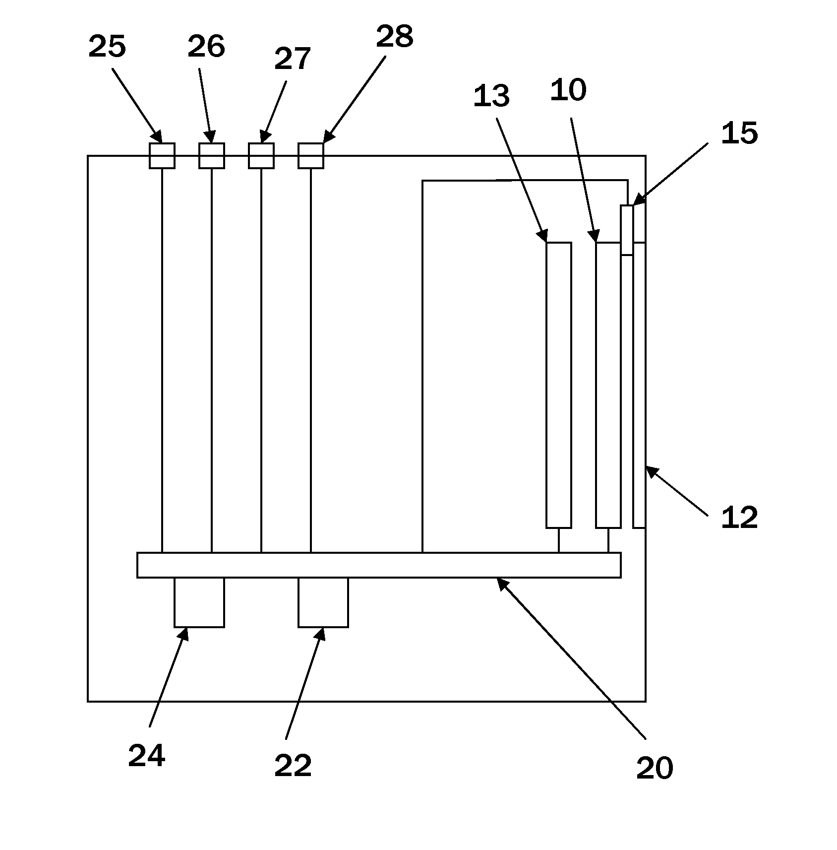
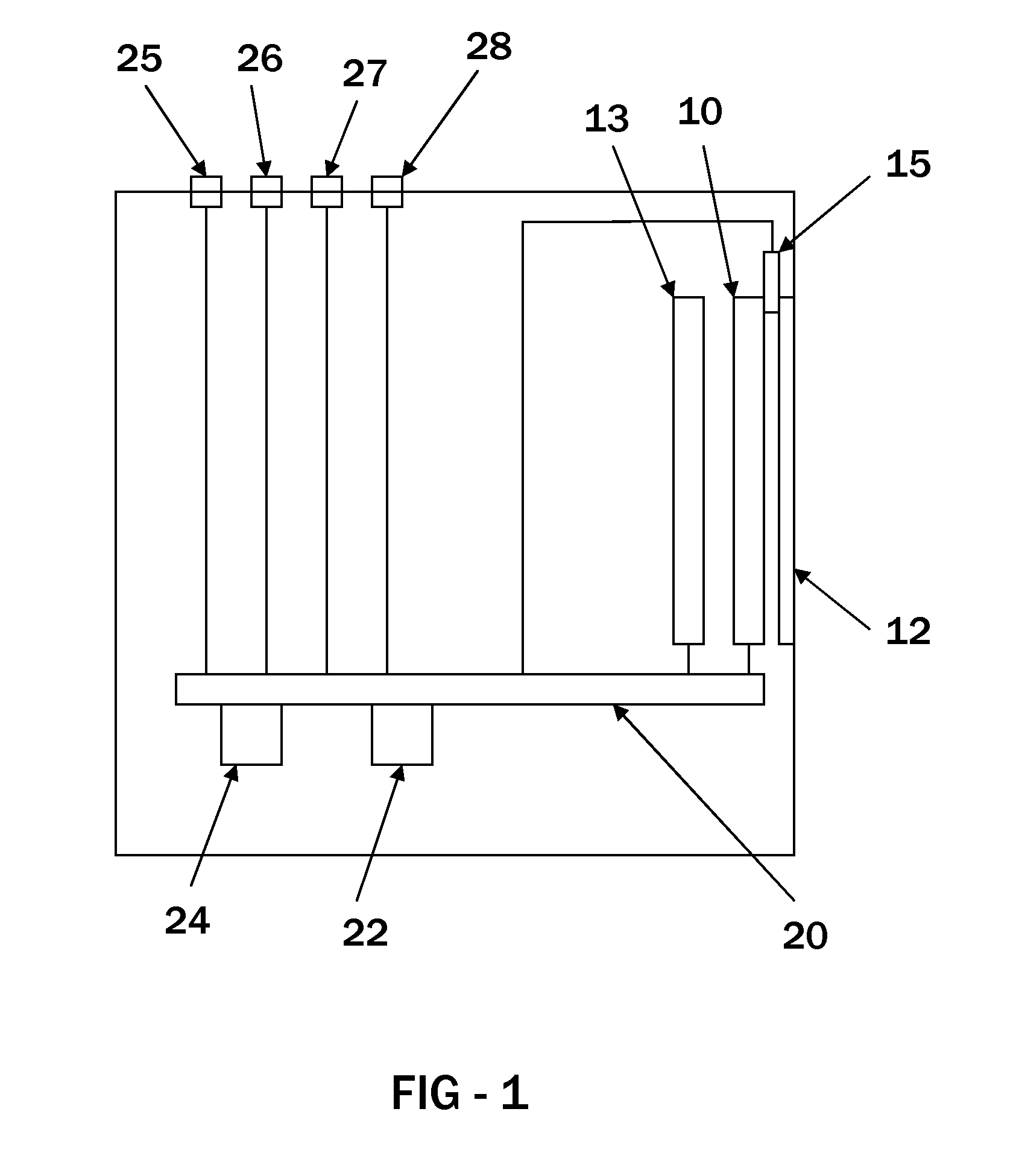
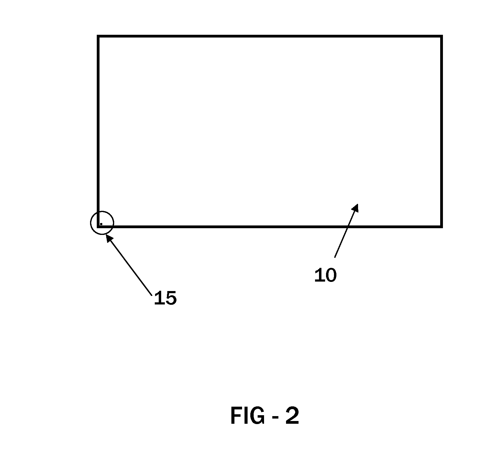
[0005]Exemplary embodiments display a watermark and measure various characteristics of the watermark through one or more color light sensors which are embedded within the display. The color light sensor provides feedback data regarding any number of performance characteristics of the display. The data may be stored internally within the display for later access by the user or may be streamed out of the display in real time to a remote storage device. The data can be used to indicate failures in some of the display componentry or the transmission of the video / audio signals and can also provide input as to the actual performance of the display. Some end-users require specific performance characteristics of their displays and embodiments help to collect the data which can determine whether the displays are meeting the required characteristics. The data can be plotted and analyzed in a number of ways to evaluate the performance of the display.
[0006]The foregoing and other features and a...
PUM
 Abstract
Description
Claims
Application Information