

Rotor Lock for a Wind Turbine
a technology of rotating locking and wind turbine, which is applied in the direction of propellers, propulsive elements, water-acting propulsive elements, etc., can solve the problems of unreliable rotational locking, difficult and relatively expensive hub manufacturing, and inability to use the locking mechanism directly for absorbing tilt or yaw loads, etc., to achieve the effect of reducing the risk
- Summary
- Abstract
- Description
- Claims
- Application Information
AI Technical Summary
Benefits of technology
Problems solved by technology
Method used
Image

Examples
Embodiment Construction
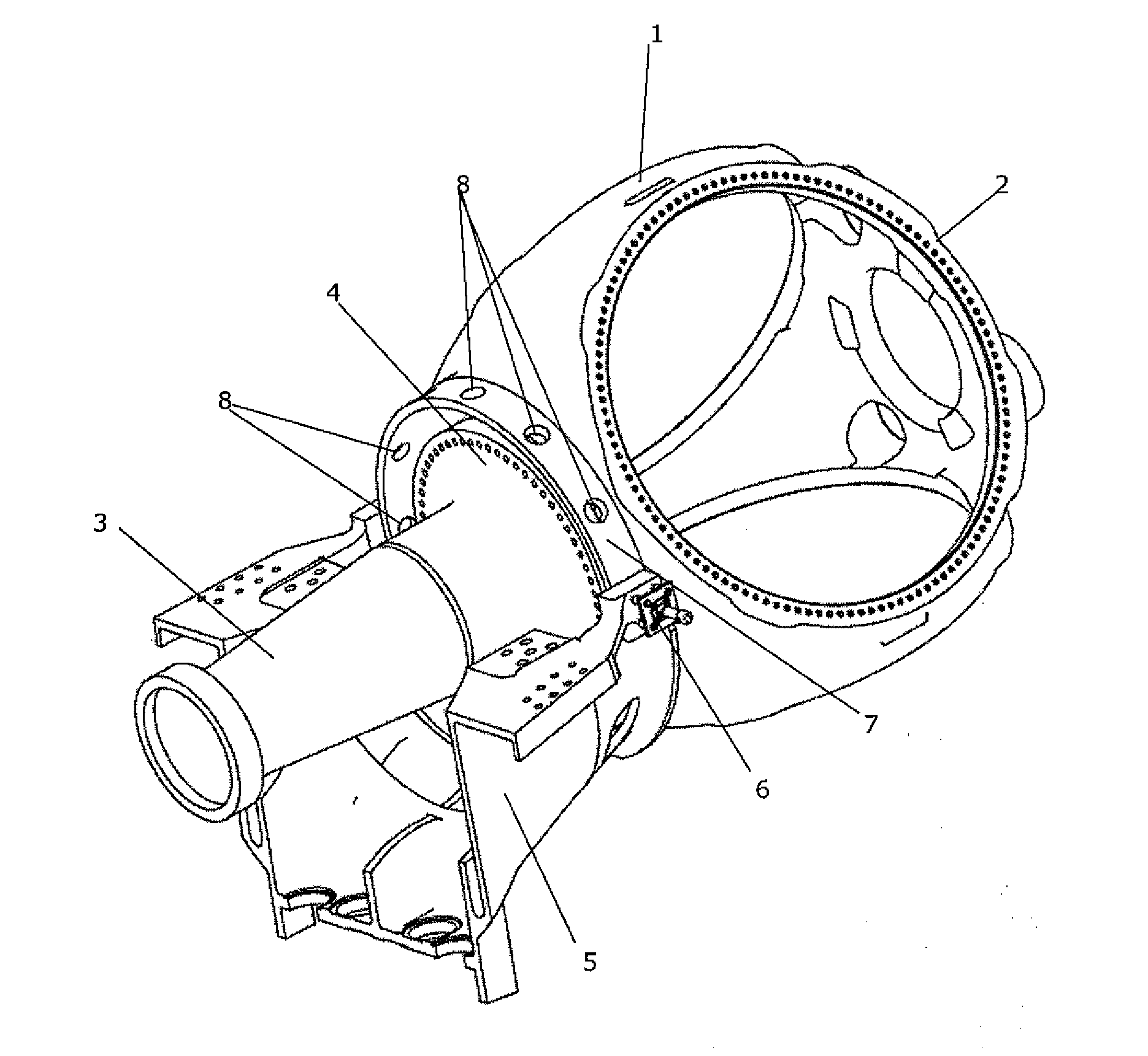
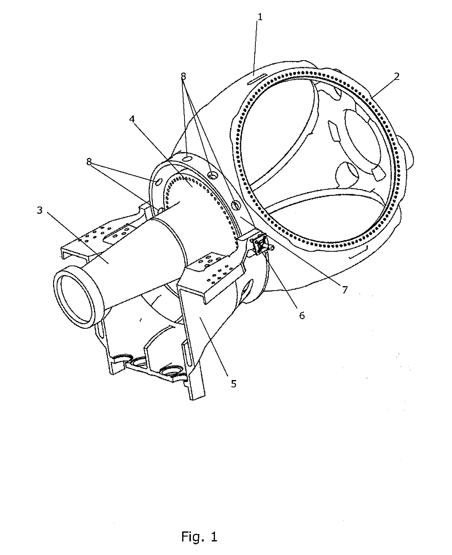
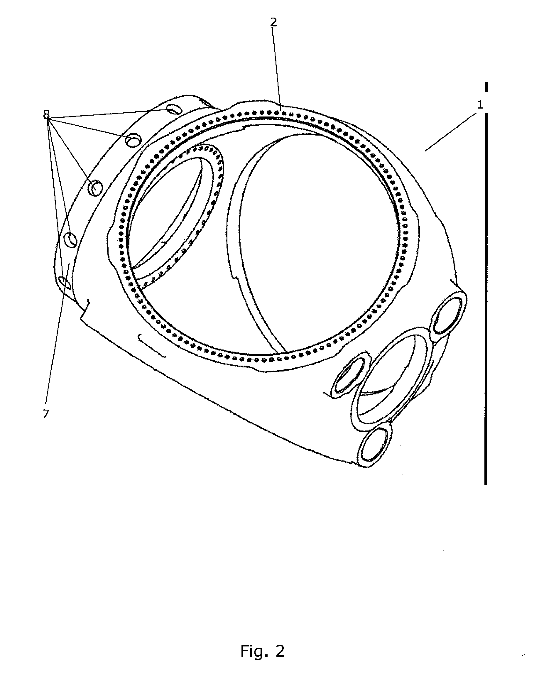
[0008]It is an object of the invention to provide a locking arrangement for a hub of a wind turbine which is capable of preventing rotational movements of the hub as well as tilt and / or yaw movements of the hub.
[0009]It is a further object of the invention to provide a locking arrangement for a hub of a wind turbine which is capable of preventing rotational movements of the hub during removal or replacement of the main shaft.
[0010]It is an even further object of the invention to provide a locking arrangement for a hub of a wind turbine in which rotational locking of the hub is more reliable than the locking provided by prior art locking arrangements.
[0011]It is an even further object of the invention to provide a locking arrangement for a hub of a wind turbine, wherein the locking arrangement is easier and more cost effective to manufacture than prior art locking arrangements.
[0012]According to the invention there is provided a locking arrangement for a hub of a wind turbine, said h...
PUM
 Abstract
Description
Claims
Application Information