Fixation arrangement for an oil pump in a refrigeration compressor

a technology for fixing arrangements and compressors, which is applied in the direction of machines/engines, liquid fuel engines, positive displacement liquid engines, etc., can solve the problems of affecting the centrifugal effect, affecting the service life of the oil pump, etc., to ensure a reliable, strong and correct retention, and reduce the cost of machining. , the effect of reducing the cos

Inactive Publication Date: 2010-09-16
WHIRPOOL SA
View PDF2 Cites 8 Cited by
  • Summary
  • Abstract
  • Description
  • Claims
  • Application Information

AI Technical Summary

Benefits of technology

[0012]It is an object of the present invention to provide a fixation arrangement for an oil pump in a refrigeration compressor which allows and guar

Problems solved by technology

In low rotation operations, this centrifugal effect is impaired, it being necessary to develop other pumping principles in order to comply with the lubrication demand.
Since the tubular sleeve of the oil pump rotates with full compression of the centrifugal force, the oil ascends through the helical groove without escaping therefrom, as the centrifugal force pushes the oil to the bottom of the channel and the side walls of said helical groove do not allow the oil to descend gravitationally.
However, the machining of the helical groove in a tubular sleeve made of metallic material is extremely difficult, expensive and complex.
Nevertheless, affixing the tubular sleeve made of plastic material directly in the inte

Method used


Image

  • Fixation arrangement for an oil pump in a refrigeration compressor
  • Fixation arrangement for an oil pump in a refrigeration compressor
  • Fixation arrangement for an oil pump in a refrigeration compressor

Examples


Embodiment Construction

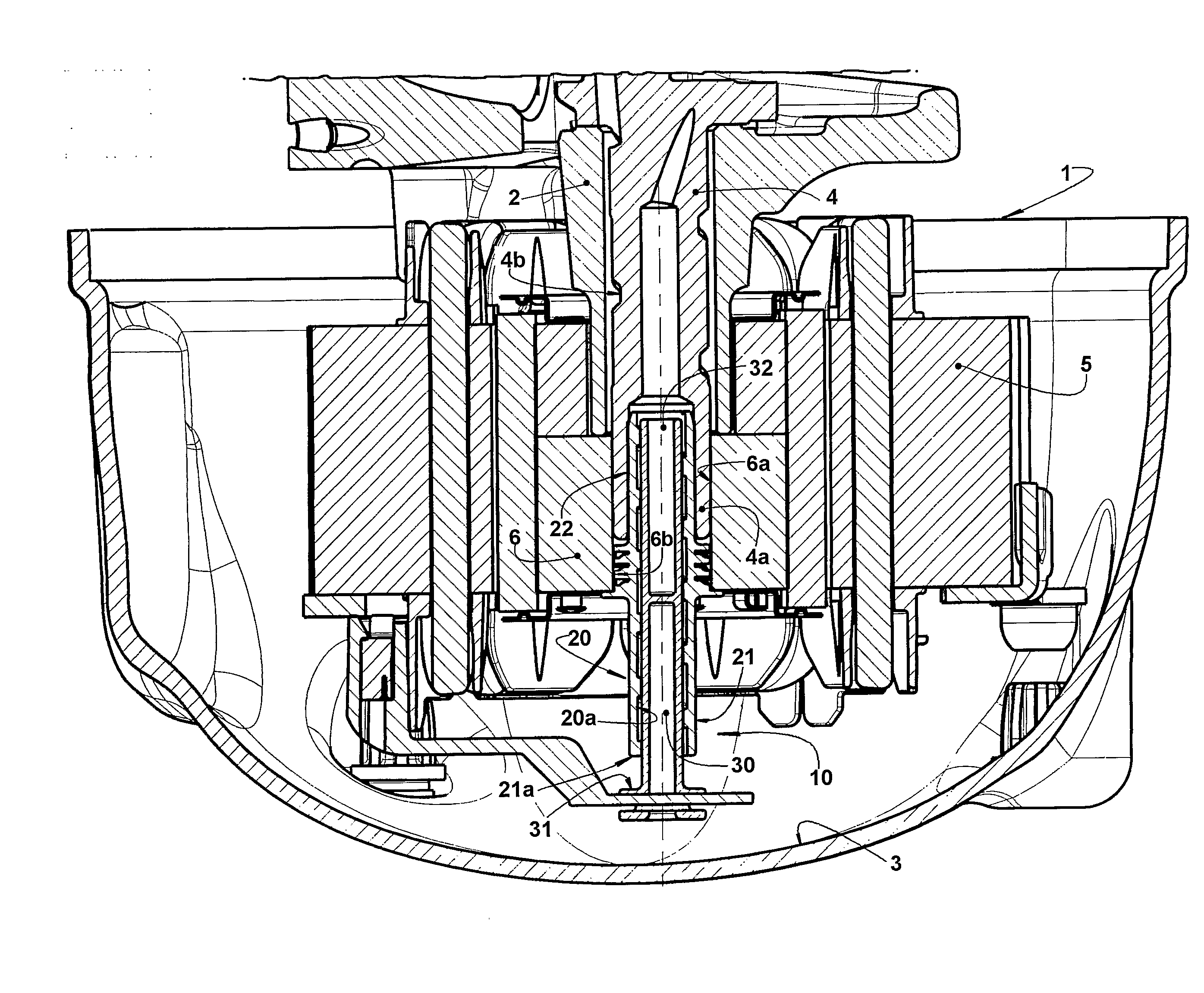
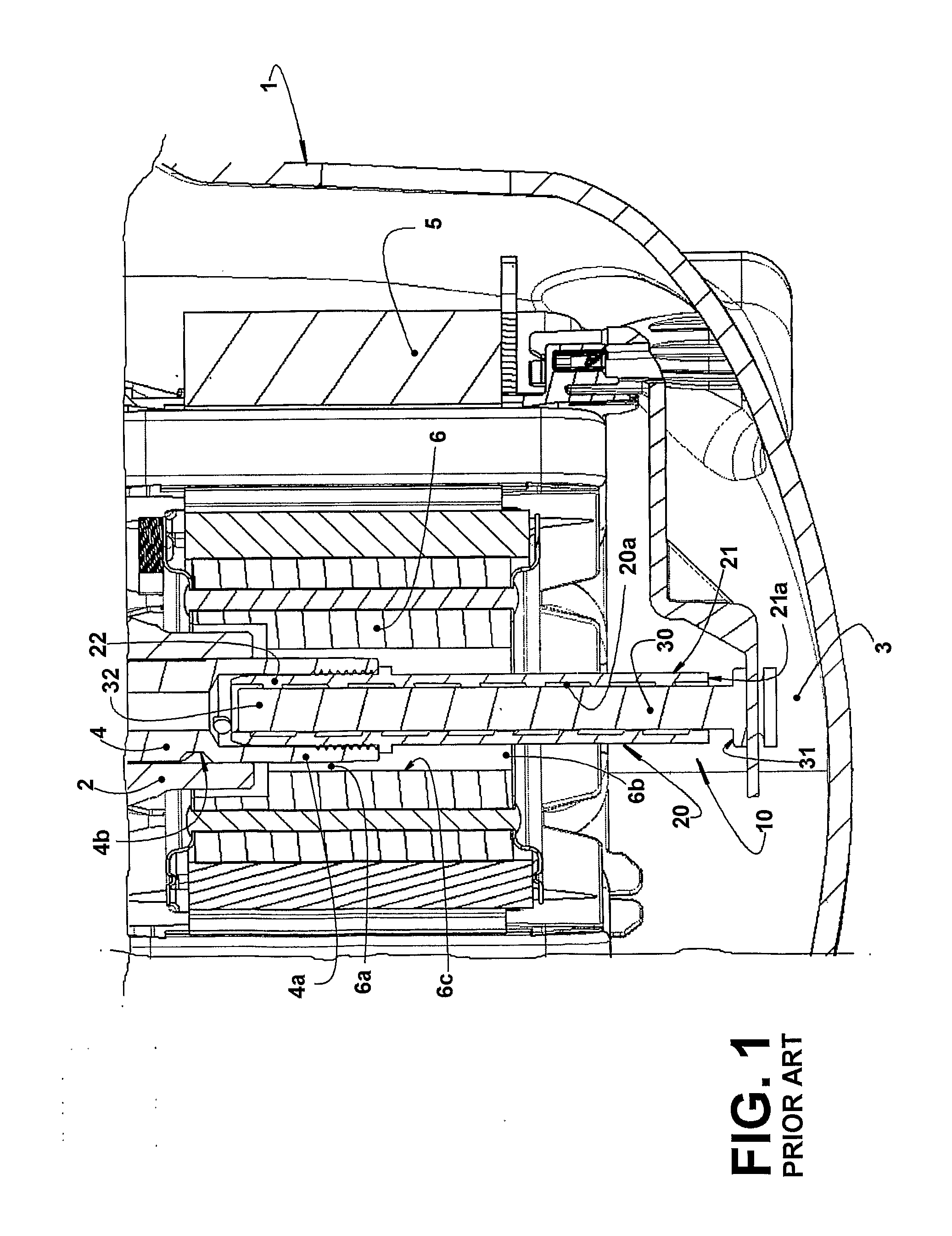
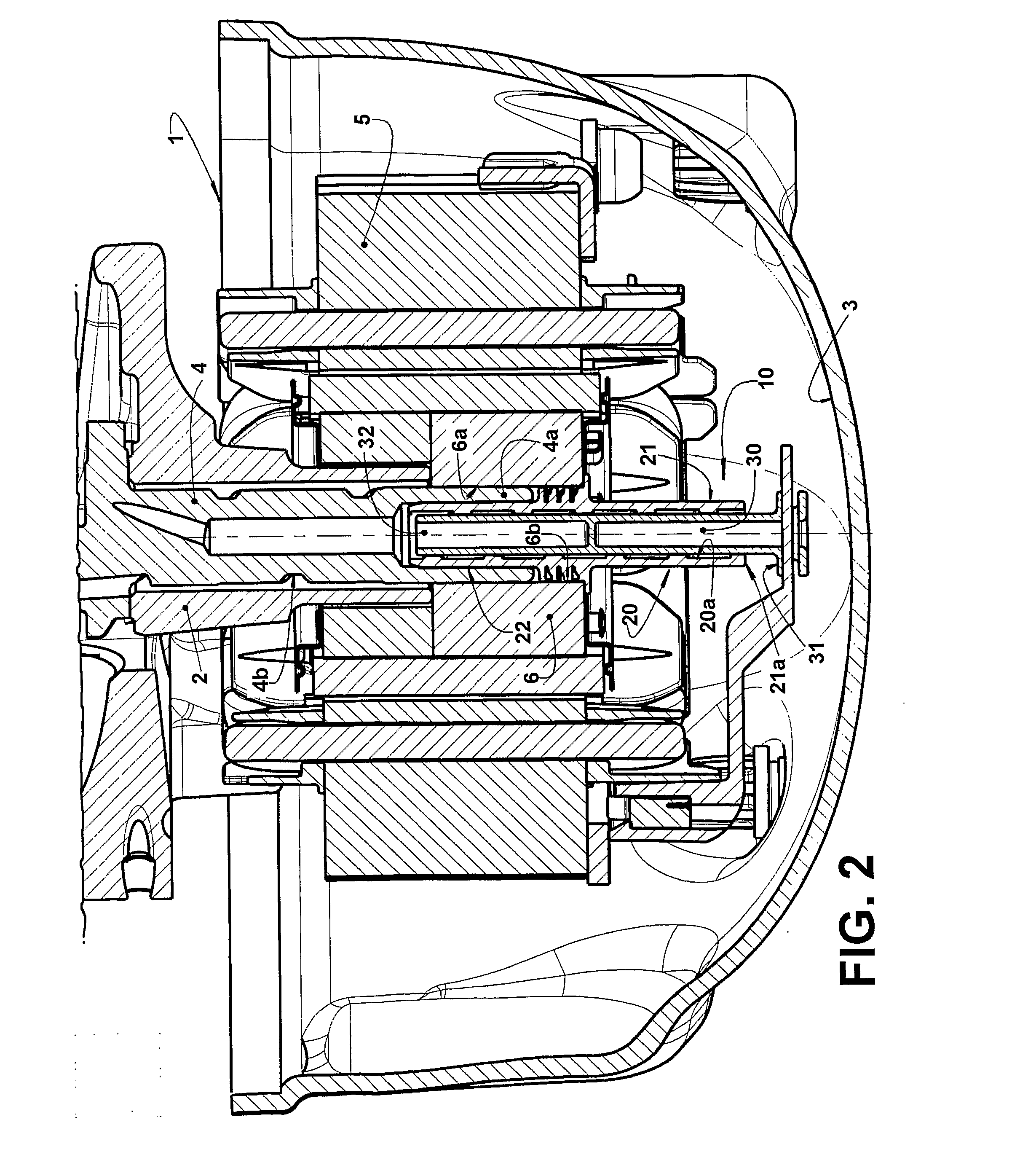
[0034]The present invention will be described for a reciprocating hermetic compressor (for example of the type applied to a refrigeration system) presenting a generally hermetic shell 1 carrying a cylinder block 2 which defines a cylinder within which actuates a reciprocating piston (not illustrated). In an inner lower portion of the shell 1 is defined an oil sump 3, wherefrom the lubricant oil is pumped, by an oil pump 10, to the compressor movable parts.

[0035]In the construction described herein, the refrigeration compressor is of the type which is driven by a crankshaft 4 which moves the piston, said crankshaft 4 superiorly presenting an eccentric portion (not illustrated) and being medianly journalled to the cylinder block 2 and having a lower portion projecting donwards from the cylinder block 2 and carrying the oil pump 10.

[0036]The cylinder block 2 secures a stator 5 of an electric motor, further including a rotor 6 attached to the crankshaft 4, so as to rotate the latter upo...


PUM


Abstract

The fixation arrangement of the present invention is applied to a compressor of the type which comprises a shell (1) inferiorly defining an oil sump (3) and housing: a crankshaft (4) journalled in a cylinder block (2) and carrying a rotor (6) formed by a stack of annular laminations; and an oil pump (10) comprising a tubular sleeve (20), which is superiorly mounted to the rotor (6) and inferiorly immersed in the oil sump (3), and a pump shaft (30). The fixation arrangement comprises at least one retention element (40) radially and axially locked around the tubular sleeve (20) and having a radially outer locking portion (41), which is seated and radially forced against a respective confronting circumferential extension (6c) defined between two consecutive annular laminations, in order to axially lock the tubular sleeve (20) to the rotor (6).

Description

FIELD OF THE INVENTION[0001]The present invention refers to a fixation arrangement for an oil pump in a refrigeration compressor of the type which comprises, in the interior of a generally hermetic shell inferiorly defining an oil sump and carrying: a cylinder block in which is journalled a crankshaft, for driving a refrigerant gas pumping mechanism of the compressor, and carrying an electric motor rotor, formed by a stack of annular laminations and further carrying, inferiorly, an oil pump which comprises a tubular sleeve, superiorly mounted to the rotor and inferiorly immersed in the oil sump, and a stationary pump shaft, internal to the tubular sleeve, defining an annular gap with the inner wall of the latter and having a lower end supported by one of the parts of shell and cylinder block. In a more specific form, the present invention refers to a fixation arrangement of the oil pump to the rotor.BACKGROUND OF THE INVENTION[0002]An important factor for the correct operation of th...

Claims


Application Information

Patent Timeline
IPC IPC(8): F01C21/04
CPCF04B39/123F04B39/0261
Inventor SILVA, FABIANO DOMINGOSJOVITA, LUIS FABIANORIBAS, JR., FERNANDO ANTONIOLOPES, ANDREAKLEIN, FABIO HENRIQUEHUELSE, EMILIO RODRIGUES
Owner WHIRPOOL SA
Why Eureka
Try Eureka