Devices and Methods For Occluding a Flexible Tube

Active Publication Date: 2010-09-16
DEKA PROD LLP
View PDF54 Cites 14 Cited by
  • Summary
  • Abstract
  • Description
  • Claims
  • Application Information

AI Technical Summary

Benefits of technology

[0005]The present invention is directed to a device and method for occluding or constricting the lumen of a segment of a flexible tube. In some applications, such a device will help prevent accidental blood loss by occluding flexible tubing coupled to an intravenous catheter or needle. The occlusion can be partial or complete. In either case, the increase in flow resistance or change in intraluminal pressure can be detected by appropriate sensors in the fluid line, resulting in the generation of a pump controller alarm and a pump shutdown signal. A device having features of the present inv

Problems solved by technology

It is much more difficult, however, to detect dislodgement of a venous needle or catheter.
This risk is heightened when a patient is asleep or otherwise unaware that tension applied to the intravenous line has resulted in dislodgement of the IV needle.
Current dialysis systems cannot readily detect when an indwelling venous IV needle delivering blood from the dialysis machine to the pa

Method used


Image

  • Devices and Methods For Occluding a Flexible Tube
  • Devices and Methods For Occluding a Flexible Tube
  • Devices and Methods For Occluding a Flexible Tube

Examples


embodiment 300

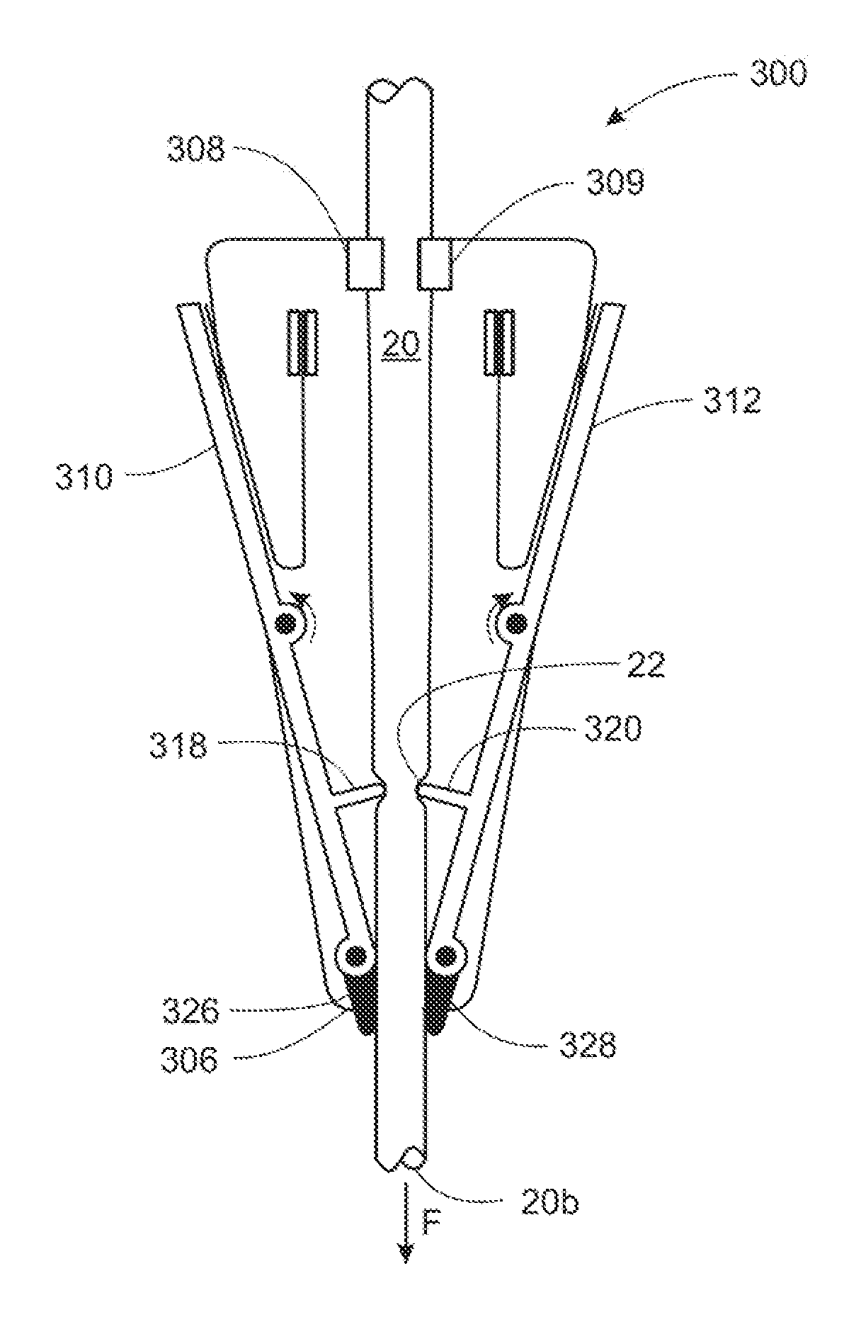
[0167]As shown in FIG. 21, the embodiment 300 is shown in an occluded position. When a predetermined threshold force F acts on the second end 20b, the slack 21 in tube 20 is removed and the tube generally moves towards the second peripheral edge 306. Since triggering arms 326 and 328 engage the tube, a longitudinal movement of tube 20 acts to rotate arms 326 and 328. The rotation of the triggering arms leads to the rotation of the support arms 310 and 312; and under the force of springs 324 and 326, occluding members 318 and 320 apply an occlusive force against the sides of tube 20.

[0168]As shown in FIG. 22, another embodiment 400 of a device for occluding a flexible tube generally comprises two bodies 402 and 404 pivotally connected by a central hinge 410. A first clip 406 is mounted to body 402 and second clip 408 is mounted to body 404 to hold the tube 20 in a first position 21 between the clips. Strain relief is provided when the tube 20 is in the first position 21 in order for ...

embodiment 500

[0169]As shown in FIG. 25, another embodiment 500 of a device for occluding a flexible tube generally comprises a hollow cylindrical body 502 having a first circular edge 504 and a second circular edge 505 located at opposite ends of the body. Semicircular arms 506 and 508 are connected to and extend away from the second peripheral edge 505. An elastic actuating member 520 is located at the distal ends of the arms 506 and 508 and is capable of deflecting the distal ends of the arms toward each other. Actuating member 520 may alternatively be any element that exerts a spring-like force to compress the distal ends of arms 506 and 508 toward each other, such as, for example, a metallic spring clip. The arms 506 and 508 are capable of bending towards each other resulting in the occlusion of the tube 20 and then returning to their original position. A first occluding member 510 and a second occluding member 512 are attached to the first arm 506 and the second arm 508 respectively. The oc...

embodiment 1200

[0186]As shown in FIGS. 45 and 46, another embodiment 1200 of a device for occluding a flexible tube generally comprises a first body 1202 having a generally planar surface; a second body 1206 pivotably attached to the first body 1202; a plunger 1220 slideably attached to the first body 1202; and compression spring 1230 positioned between the plunger and the first body. A first channel 1204 having two curved sidewalls for positioning a tube 20 therebetween is located at one end of the first body 1202, while a curved member 1210 is attached to the opposite end of the first body 1202. Additionally, a plunger 1220 is slideably mounted on the first body 1202 where the compression spring 1230 provides the force necessary to move the plunger 1220 into the first channel 1204 and occlude the tube located therein.

[0187]As shown in FIGS. 45 and 46, in a first position, the spring 1230 is compressed against the curved member 1210 and the plunger 1220. It is restrained by a tab 1224 extending f...


PUM


Abstract

A device and method to constrict or occlude the lumen of a flexible tube may include an occluder under the influence of an elastic force, such as a spring force, that can compress a portion of the wall of the flexible tube. The occluder can be under the influence of the elastic force, but prevented from occluding the tube by a stop. The stop can be connected to a tube gripping feature, so that a pulling force on the tube near the gripping feature can disengage the stop from the occluder, releasing the occluder to compress the tube. In some embodiments, the pulling force applied to the tube causes movement of the gripping feature by taking up slack in a portion of the tube held in the device. In other embodiments, the pulling force applied to the tube causes the tube to stretch elastically near the gripping feature, causing the gripping feature to move, and disengaging the stop from the occluder.

Description

RELATED APPLICATIONS[0001]This application claims priority from U.S. Provisional Patent Application No. 61 / 158,174, filed Mar. 6, 2009, and entitled Device and Method for Occluding a Flexible Tube, which is incorporated by reference herein in its entirety.FIELD OF THE INVENTION[0002]The invention relates to devices and methods for occluding or constricting the lumen of a segment of flexible tubing by compressing the wall of the tubing. In an exemplary application, it relates to the partial or complete occlusion of flexible tubing in fluid communication with the blood vessel of a patient.BACKGROUND[0003]Systems that use flexible tubes to transfer fluids from one location to another frequently take advantage of the compressibility of the tubes to adjust, restrict or stop fluid flow within them. This is particularly useful in medical applications in which biological or therapeutic fluids are transferred between a source or destination and a patient by means of an electro-mechanical ins...

Claims


Application Information

Patent Timeline
IPC IPC(8): A61M39/00
CPCF16K7/06A61M39/281F16K7/063
Inventor KENLEY, RODNEY S.KAMEN, DEANVIOLETTE, KEITH D.GRANT, KEVIN L.GRAY, LARRY B.LANIGAN, RICHARD J.DEMERS, JASON A.
Owner DEKA PROD LLP
Why Eureka
Try Eureka