Door transport and installation system

a door and installation system technology, applied in the field of building construction and maintenance, can solve the problems of lateral stability of objects that cannot be solved, tedious inserting of hinge pins, lack of solution, etc., and achieve the effect of reducing the tipping of the door, convenient hinge attachment, and convenient angular alignmen

Inactive Publication Date: 2010-09-23
CAMPBELL LARRY CHARLES
View PDF13 Cites 2 Cited by
  • Summary
  • Abstract
  • Description
  • Claims
  • Application Information

AI Technical Summary

Benefits of technology

[0011]The present invention is a Door Transporting and Installation System for use in building construction and maintenance. Generally, the instant invention solves the problem of transporting and lifting wide and narrow doors by being removably attached to a hand cart, adjusting to the width of the door to reduce tipping of the door during installation and by lifting the door in a straight upward motion utilizing a pressurized air actuator. In addition to solving these problems added features that transport the door from the delivery to the work site going easily through door ways, placing the door in a position to facilitate attachment of hinges and easy angular alignment of the door to the door jam for fastening are also provided.
[0012]The preferred embodiment of the present invention provides additional unique features by having stationery guides keeping the door moving vertically during lifting and offering a simplified model for work where the doors are separately delivered to the work site. The primary objective of the present invention is to ease the difficult task of positioning a door that can weigh two hundred pounds into a position where screws line up and to reduce the fatigue of transporting these unwieldy objects.
[0014]A further objective of the present invention is to reduce manufacturing cost by utilizing a commercially available lift cart in the product.
[0015]A further objective of the present invention is to reduce handling of the door thereby reducing the opportunities to damage the door finishes.

Problems solved by technology

However, the disclosure of inventor Simmons et al. lacks a solution to the problems of lateral stability of the object being lifted.
However, the disclosure of inventor Pohl lacks a solution to the problems of transporting the door to the work sight, holding the door in position for installation of the hinges and requires separating the hinge into two pieces and tedious inserting the hinge pin to hang the door.
However, the disclosure of inventor Wilston et al. lacks a solution to the problems of transporting wide and narrow doors, lifting the door straight up for alignment of the door mountings and ease of angular movement of the door to adjust to door jam orientation.

Method used


Image

  • Door transport and installation system
  • Door transport and installation system
  • Door transport and installation system

Examples


Embodiment Construction

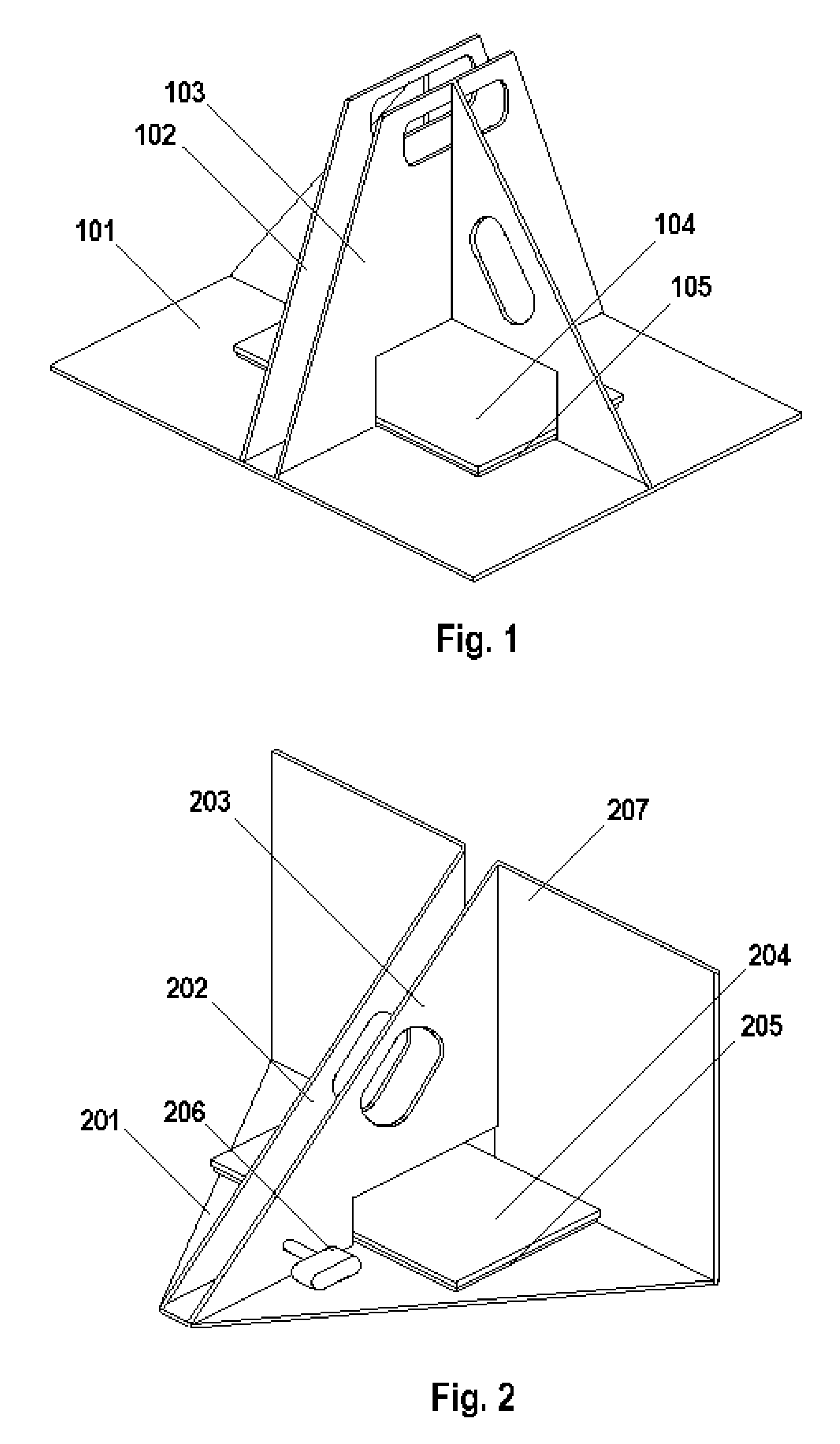
[0021]The first preferred embodiment of the present invention is shown in FIG. 1 with base 101 resting on the floor or other essentially horizontal surface. First vertical guide 102 and second vertical guide 103 extend in an essentially vertical direction from the base 101 forming a vertical space there between for guiding an object that is to be transported and lifted. The surfaces of the first vertical guide 102 and second vertical guide 103 may be lined with carpeting or other protective material to reduce the potential for damaging the doors during handling. The hose and pump for pressurizing the actuator and the valve for relieving the pressure on the actuator are (un-shown).

[0022]The second preferred embodiment of the present invention is shown in FIG. 2 with base 201 resting on the floor or other essentially horizontal surface. First vertical guide 202 and second vertical guide 203 extend in an essentially vertical direction from the base 201 forming a vertical space there be...


PUM


Abstract

Disclosed is a transport and installation system that serves the purpose of convenient moving doors from the delivery to the place of installation, positioning doors for ease of hinge installation and providing for horizontal, straight vertical and angular position of the doors with the door jam for installation of the hinge mountings. The new and unique air actuator utilizes a base, stationery vertical guides and removable attachment to a hand cart to solve the problem of handling these heavy unwieldly objects.

Description

CROSS-REFERENCE TO RELATED APPLICATIONS[0001]Not ApplicableSTATEMENT REGARDING FEDERALLY SPONSORED RESEARCH OR DEVELOPMENT[0002]Not ApplicableTHE NAMES OF THE PARTIES TO A JOINT RESEARCH AGREEMENT[0003]Not ApplicableINCORPORATION-BY-REFERENCE OF MATERIAL SUBMITTED ON A COMPACT DISC[0004]Not ApplicableBACKGROUND OF THE INVENTION[0005]1. Field of the Invention[0006]The present invention represents a significant step forward in the field of building construction and maintenance involving door installation and repair. Currently marketed hand cart and lifter apparatus sold for the purpose of door transport and installation do not address the problems of a door installer being able to transport wide doors or to lift the door straight up for convenient positioning of the door for hinge installation as well as the freedom to adjust the door position angularly for alignment with the door jam during installation. Recent declines in the price of residential and commercial buildings will increa...

Claims


Application Information

Patent Timeline
Patent Type & Authority Applications(United States)
IPC IPC(8): E04G21/14E04G21/00B62B1/26B62B1/00B66F3/35
CPCB62B1/12B62B2203/10B62B1/268
Inventor CAMPBELL, LARRY CHARLES
Owner CAMPBELL LARRY CHARLES
Why Eureka
Try Eureka