High-Speed, Low-Power Driver System

a driver system and high-speed technology, applied in pulse generators, pulse techniques, instruments, etc., can solve problems such as unmet needs relating to data storage devices

Active Publication Date: 2010-09-23
TEXAS INSTR INC
View PDF5 Cites 13 Cited by
  • Summary
  • Abstract
  • Description
  • Claims
  • Application Information

AI Technical Summary

Problems solved by technology

Consequently, there remain unmet nee

Method used


Image

  • High-Speed, Low-Power Driver System
  • High-Speed, Low-Power Driver System
  • High-Speed, Low-Power Driver System

Examples


Embodiment Construction

[0017]As used in the specification and the appended claim(s), the singular forms “a,”“an” and “the” include plural referents unless the context clearly dictates otherwise. Similarly, “optional” or “optionally” means that the subsequently described event or circumstance may or may not occur, and that the description includes instances where the event or circumstance occurs and instances where it does not.

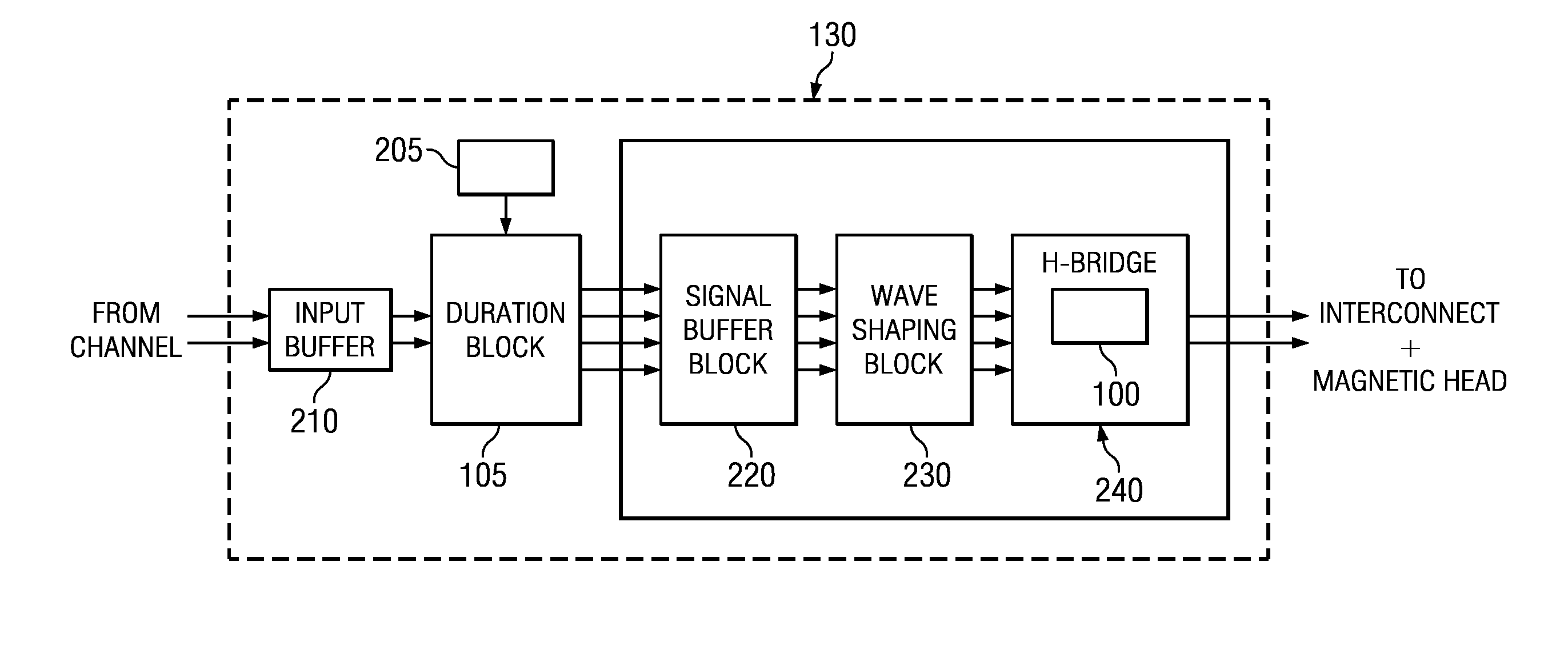
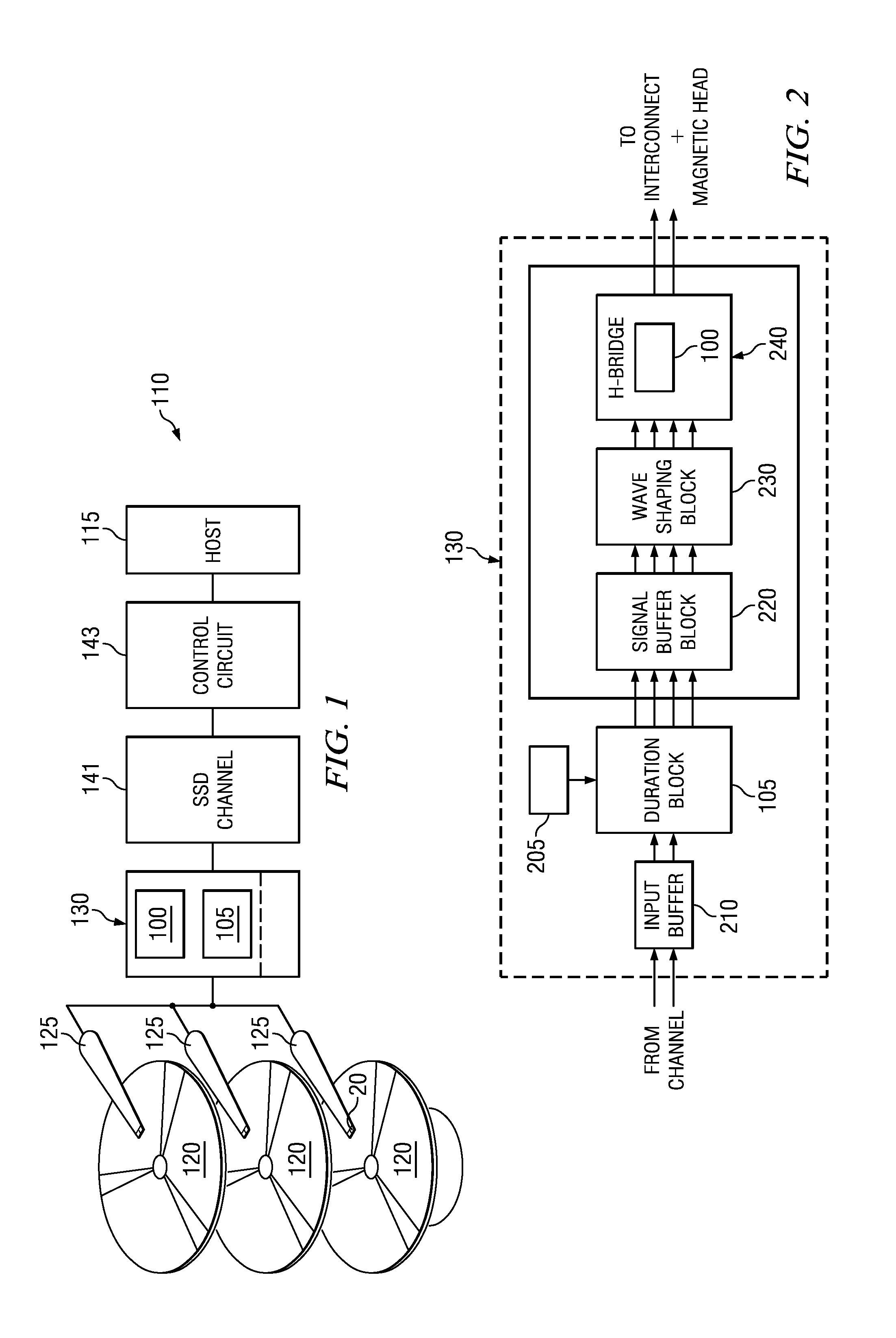
[0018]FIG. 1 is an environmental drawing of a high-speed, low-power driver system illustrating a reduced power driver (RPD) 100 and a duration-block 105 of a data storage system 110. A host 115 (e.g., a computer system) may initiate commands that facilitate storing or retrieving data from a media 120 (e.g., a magnetic platter). In this implementation, the data storage system 110 may have a head 125 associated with each media 120 used during data storage or retrieval. If data is represented as magnetic transitions on this media, the heads 125 may be magneto-resistive heads for reading...


PUM


Abstract

A reduced power driver is described. This reduced power driver comprises: an input current driver for transmitting a current signal that is a fraction of a DC current signal; a first resistor coupled at one end to a first voltage supply; a first current driver coupled to the input current driver and a first switch control; a second switch coupled a first current driver output, another end of the first resistor, and the output control; a dynamic booster coupled between the first voltage supply and the output control; and wherein the reduced power driver is operative for selectively adding an overshoot current to the output control so that power consumption is reduced, while synchronizing the DC current signal with the overshoot current.

Description

CROSS REFERENCE TO RELATED APPLICATION(S)[0001]The present application claims priority to jointly owned U.S. Provisional Application corresponding to application No. 61 / 162,067 entitled “Techniques for Fast Preamplifier Writer.” This provisional application was filed on Mar. 20, 2009.DESCRIPTION OF RELATED ART[0002]With the evolution of electronic devices, there is a continual demand for enhanced speed, capacity and efficiency in various areas including electronic data storage. Motivators for this evolution may be the increasing interest in video (e.g., movies, family videos), audio (e.g., songs, books), and images (e.g., pictures). Hard disk drives have emerged as one viable solution for supplying high capacity storage by effectively reading and writing data from an associated magnetic media. As the densities of magnetic media increases, it becomes increasingly important that both the writing process and the reading process can accommodate increasing data rates, without sacrificing...

Claims


Application Information

Patent Timeline
IPC IPC(8): H03B1/00
CPCH03F3/45085H03F2203/45636H03F3/45282
Inventor MUKHOPADHYAY, RAJARSHIPANDEY, PANKAJSHARIFI, REZA
Owner TEXAS INSTR INC
Why Eureka
Try Eureka