
Zoom lens

Active Publication Date: 2010-09-23
OM DIGITAL SOLUTIONS CORP
View PDF1 Cites 9 Cited by
  • Summary
  • Abstract
  • Description
  • Claims
  • Application Information

AI Technical Summary

Benefits of technology

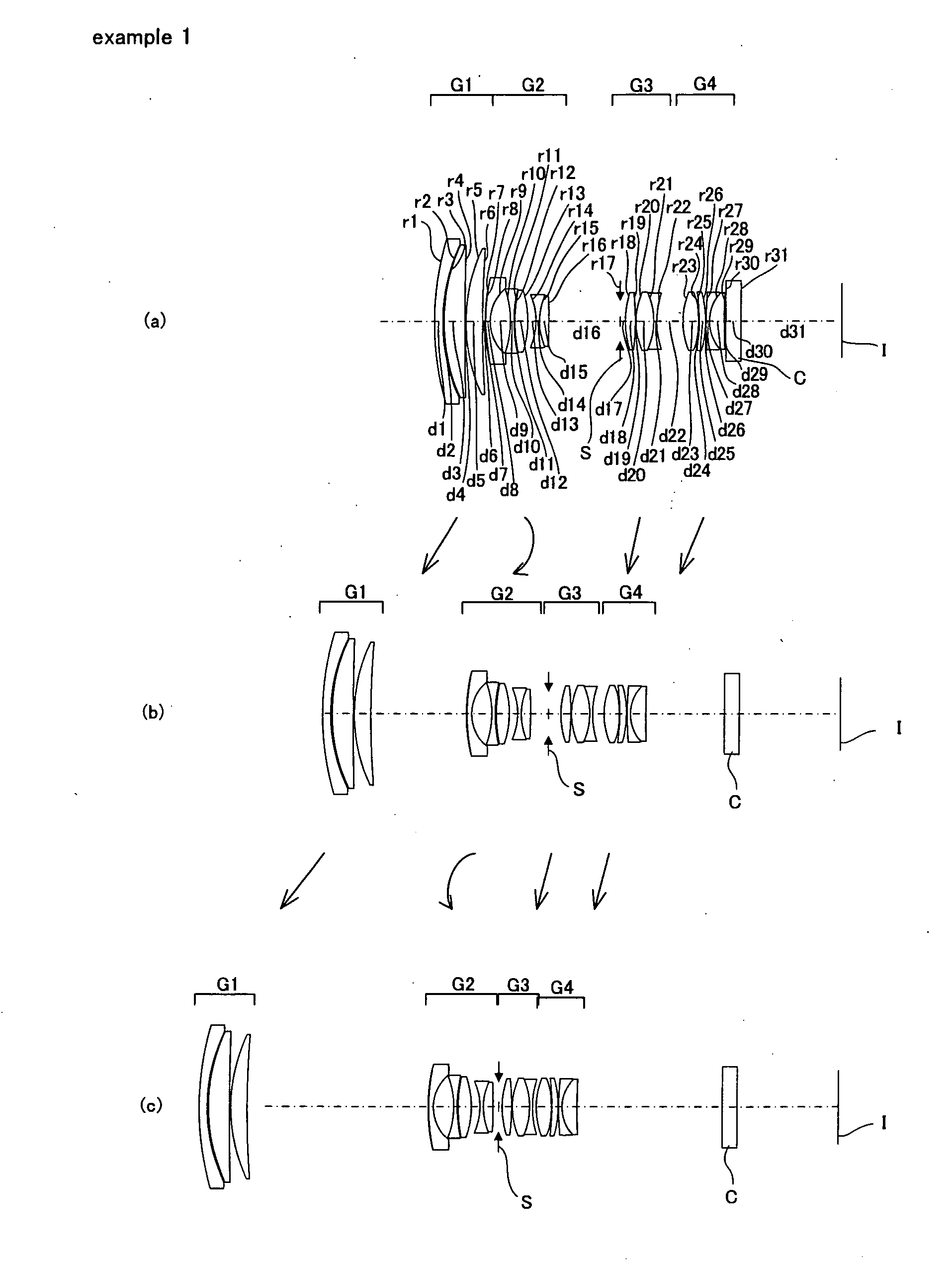
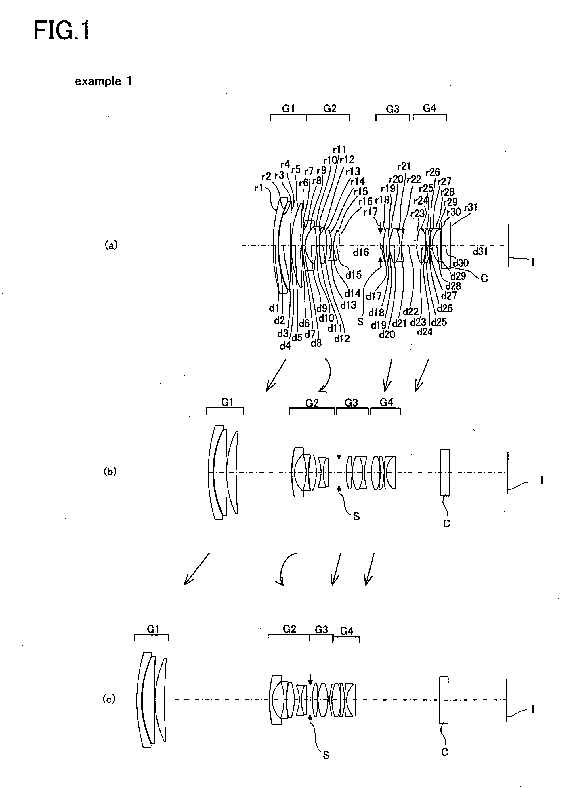
[0032]For a third configuration, a zoom lens, from an object side in the following order, includes: a first lens group that has a positive refractive power; a second lens group that has a negative refractive power; a third lens group that has a positive refractive power; and a fourth lens group that has a positive refractive power, wherein: when magnification is changed from a wide angle end to a telephoto end, the lens groups each move so as to increase the distance between the first and second lens groups and to decrease the distance between the second and third lens groups and the distance between the third and fourth lens groups; and the second lens group moves so as to leave a convex track at the object side after moving so as to leave a convex track at an image side.
[0037]The following describes the reason why the second lens group moves around the telephoto end so as to leave a convex track at the object side when magnification is changed. When magnification is changed, around the telephoto end, the action of changing magnification by moving the second lens group to the image side is realized again, in order to prevent an increase in the overall length due to the excessively widened space between the first and second lens groups; it is desirable that the increase in the overall length at the telephoto end, which could be caused by the widened space between the first and second lens groups, be controlled. As a result, the second lens group reverses the course again to move so as to leave a track at the image side, making it possible to keep the balance between downsizing of the lens barrel and correction of aberration.
[0068]Furthermore, in the zoom lens, the second lens group includes an aspheric surface, making it possible to efficiently correct mainly astigmatism, distortion, and the like. In particular, the aspheric lens is the one in the second lens group that is positioned closest to the object side, making it possible to efficiently correct distortion and the like.
[0069]Furthermore, in the zoom lens, the fourth lens group includes an aspheric surface, making it possible to efficiently correct mainly astigmatism, coma aberration, and the like. In particular, the aspheric lens has a positive power and is the one in the fourth lens group that is positioned closest to the object side, making it possible to efficiently correct coma aberration and the like. Moreover, when the aspheric lens is positioned closest to the image side in the fourth lens group, it is possible to efficiently correct astigmatism and the like. It is more desirable that two aspheric lenses be disposed.
[0070]Furthermore, in the zoom lens, the second lens group consists of a front sub-unit having a negative refractive power and a rear sub-unit having a negative refractive power; and when a focusing operation is carried out, the entire second lens group moves in the direction of the optical axis while changing the distance between the front and rear sub-units. Therefore, it is possible to suppress and make the change of astigmatism small when a nearby object is brought into focus.
[0071]Such a configuration is more effective for a zoom lens having a high variable magnification ratio, such as one whose variable magnification ratio is greater than or equal to four. A zoom lens whose variable magnification ratio is greater than or equal to seven is more effective. A zoom lens whose variable magnification ratio is greater than or equal to ten is far more effective.

Problems solved by technology

Moreover, as for a conventional zoom lens having a high variable magnification ratio, resolution is particularly lower at a telephoto end than at a wide angle end due to the effect of chromatic aberration of magnification and the like.

Method used


Image

  • Zoom lens
  • Zoom lens
  • Zoom lens

Examples


example 1

Numeric Example 1

[0246]

Unit mmSurface dataSurface Numberrdndνd 190.6182.651.8502632.27 256.5480.45 358.7316.501.4970081.54 41683.6700.20 552.5335.201.4970081.54 6273.171variable 7 (Aspheric)90.8060.081.5194051.94 863.5731.401.8830040.76 913.0496.4810−27.4611.051.6031160.641140.6690.201240.5954.201.6889331.0713−28.664variable14−19.2081.001.6968055.531519.9383.101.8010034.9716−132.991variable17 (Stop)∞1.501828.9003.001.4970081.5419−83.0430.202022.3595.451.5826746.4221−22.2651.001.8061040.922227.235variable23 (Aspheric)20.2294.791.4970081.5424 (Aspheric)−31.0550.2025−52.4551.931.4970081.5426−33.3760.2027119.3221.001.7859044.202812.8714.601.5163364.1429339.930variable30∞4.571.5163364.1431∞31.02 Image Surface∞Aspheric data7 surfaceK = −130.000, A4 = 4.52900E−05, A6 = −2.36519E−07,A8 = 9.84174E−10, A10 = −1.91016E−1223 surfaceK = −0.858, A4 = −2.86800E−05, A6 = −2.37382E−07,A8 = −7.90089E−11, A10 = 3.47390E−1224 surfaceK = 0.000, A4 = −8.53186E−06, A6 = −3.03923E−07,A8 = 1.88936E−09, A10 ...

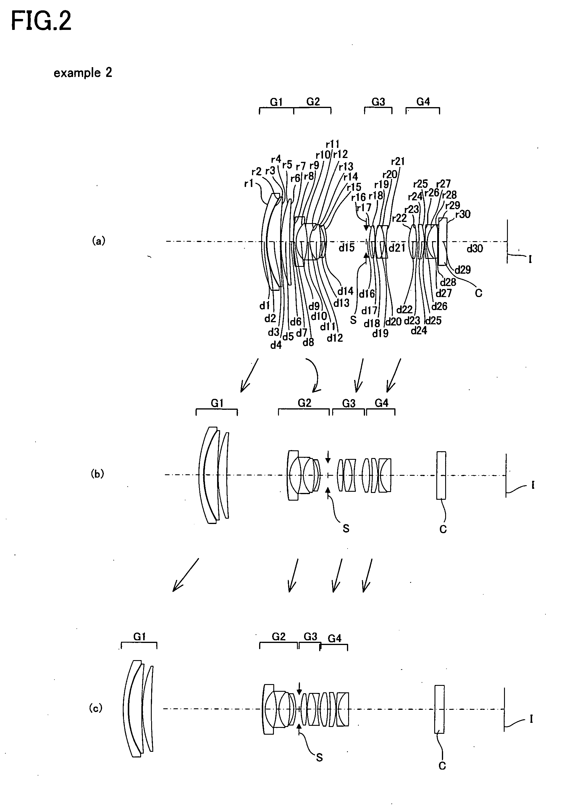
example 2

Numeric Example 2

[0247]

Unit mmSurface dataSurface Numberrdndνd 166.3282.651.8502632.27 245.4360.25 345.2507.001.4970081.54 4299.8000.20 563.1764.701.4970081.54 6335.857variable 7 (Aspheric)481.6670.081.5194051.94 886.8621.401.8830040.76 913.4365.9010−28.5371.051.6968055.531113.6370.011.5638460.701213.6376.001.7950428.5713−40.7991.8914−15.2621.001.6584450.8815−27.963variable16 (Stop)∞1.511730.2723.001.4970081.5418−62.6920.201934.2974.641.5831359.3820−19.0381.001.8040046.572144.212variable22 (Aspheric)20.0253.891.4970081.5423 (Aspheric)−60.9381.5024−65.7162.841.5163364.1425−31.1160.272690.0451.001.7880047.372712.2165.501.5163364.1428−234.323variable29∞4.571.5163364.1430∞31.02 Image Surface∞Aspheric data7 surfaceK = −8.762, A4 = 3.71514E−05, A6 = −1.08617E−07,A8 = 4.69314E−10, A10 = −5.72623E−1322 surfaceK = −0.419, A4 = −2.44119E−05, A6 = −1.87312E−07,A8 = 1.09982E−09, A10 = −3.00750E−1223 surfaceK = 0.860, A4 = −1.09348E−05, A6 = −1.78033E−07,A8 = 1.65893E−09, A10 = −4.96813E−1228 su...

example 3

Numeric Example 3

[0248]

Unit mmSurface dataSurface Numberrdndνd 1102.2392.651.8502632.27 260.4690.44 362.8396.301.4970081.54 4−5475.1940.20 553.6205.401.4970081.54 6291.069variable 7 (Aspheric)2010.5150.081.5194051.94 8100.8871.401.8830040.76 913.4345.9010−28.7831.051.6968055.531113.4980.011.5638460.701213.4986.001.7950428.5713−39.7051.8714−15.3751.001.6779050.7215−27.190variable16 (Stop)∞1.941728.9823.101.4970081.5418−66.7310.201935.6154.671.5831359.3820−18.5451.001.8040046.572143.986variable22 (Aspheric)19.5304.101.4970081.5423 (Aspheric)−48.8152.1024−50.5231.691.5163364.1425−30.8950.222688.1441.001.7880047.372712.1175.501.5163364.1428 (Aspheric)−260.135variable29∞4.571.5163364.1430∞31.02 Image Surface∞Aspheric data7 surfaceK = −99.589, A4 = 3.84229E−05, A6 = −1.00234E−07,A8 = 3.42734E−10, A10 = −3.08633E−1322 surfaceK = −0.410, A4 = −2.51348E−05, A6 = −1.87930E−07,A8 = 1.09632E−09, A10 = −2.41077E−1223 surfaceK = 0.921, A4 = −1.09550E−05, A6 = −1.77210E−07,A8 = 1.69378E−09, A10 = ...


PUM


Abstract

A zoom lens includes, from an object side in the following order: a first lens group that has a positive refractive power; a second lens group that has a negative refractive power; a third lens group that has a positive refractive power; and a fourth lens group that has a positive refractive power, wherein: when magnification is changed from a wide angle end to a telephoto end, the lens groups each move so as to increase the distance between the first and second lens groups and to decrease the distance between the second and third lens groups and the distance between the third and fourth lens groups; and the following conditional expressions (1) and (2) are satisfied:5.5<f1 / fw<8.0  (1); and0.5<Σd3 / Σd4<0.9  (2)wherefw is the focal length of the wide angle end;f1 is the focal length of the first lens group;Σd3 is the actual distance on an optical axis from the lens surface that is closest to an object to the lens surface that is closest to an image in the third lens group; andΣd4 is the actual distance on an optical axis from the lens surface that is closest to the object to the lens surface that is closest to the image in the fourth lens group.

Description

[0001]This application claims benefit of Japanese Application No. 2009-064692 filed in Japan on Mar. 17, 2009, the contents of which are incorporated by this reference.BACKGROUND OF THE INVENTION[0002]The present invention relates to a zoom lens and particularly to a zoom lens that is used in an interchangeable lens of a single lens reflex camera and the like and has a high variable magnification ratio ranging from a wide angle to a medium telephoto or telephoto range.[0003]Conventionally, as a zoom lens that is used in an interchangeable lens of a single lens reflex camera and the like and has a high variable magnification ratio covering a range of focal lengths from wide-angle to medium telephoto or telephoto, the following zoom lens, including those disclosed in JP-A-8-220439, JP-A-2003-177317, or JP-A-2003-241097, is well known: The zoom lens includes, from an object side in the following order, a first lens group having a positive refractive power, a second lens group having a ...

Claims


Application Information

Patent Timeline
IPC IPC(8): G02B15/14
CPCG02B15/173G02B15/144113
Inventor MIYAJIMA, TORU
Owner OM DIGITAL SOLUTIONS CORP
Learn More