Image forming apparatus, image forming unit, and erase light control method

a technology of image forming apparatus and image forming unit, which is applied in the direction of electrographic process apparatus, optics, instruments, etc., can solve the problems of deterioration in image quality, difficult to uniformly charge abrasion of the surface of the photoreceptor, so as to effectively prolong the lifetime of the photoreceptor. , the effect of suppressing image deterioration

Inactive Publication Date: 2010-09-23
KONICA MINOLTA BUSINESS TECH INC
View PDF6 Cites 13 Cited by
  • Summary
  • Abstract
  • Description
  • Claims
  • Application Information

AI Technical Summary

Benefits of technology

[0012]The present invention aims to realize, in an image forming apparatus having multiple photoreceptors, suppressio...

Problems solved by technology

It is difficult to uniformly charge the surface of the photoreceptor with electric charge remaining thereon partially.
This leads to deterioration in the image quality.
The surface of photoreceptors suffers abrasion due to such as a cleaning operation, and the photosensitive layer suffers fatigue, deterioration, and the like.
Thus, the lifetime of photoreceptors is limited to a particular period of time, and exposure by e...

Method used


Image

  • Image forming apparatus, image forming unit, and erase light control method
  • Image forming apparatus, image forming unit, and erase light control method
  • Image forming apparatus, image forming unit, and erase light control method

Examples


first embodiment

1-1. Overall Structure of Printer

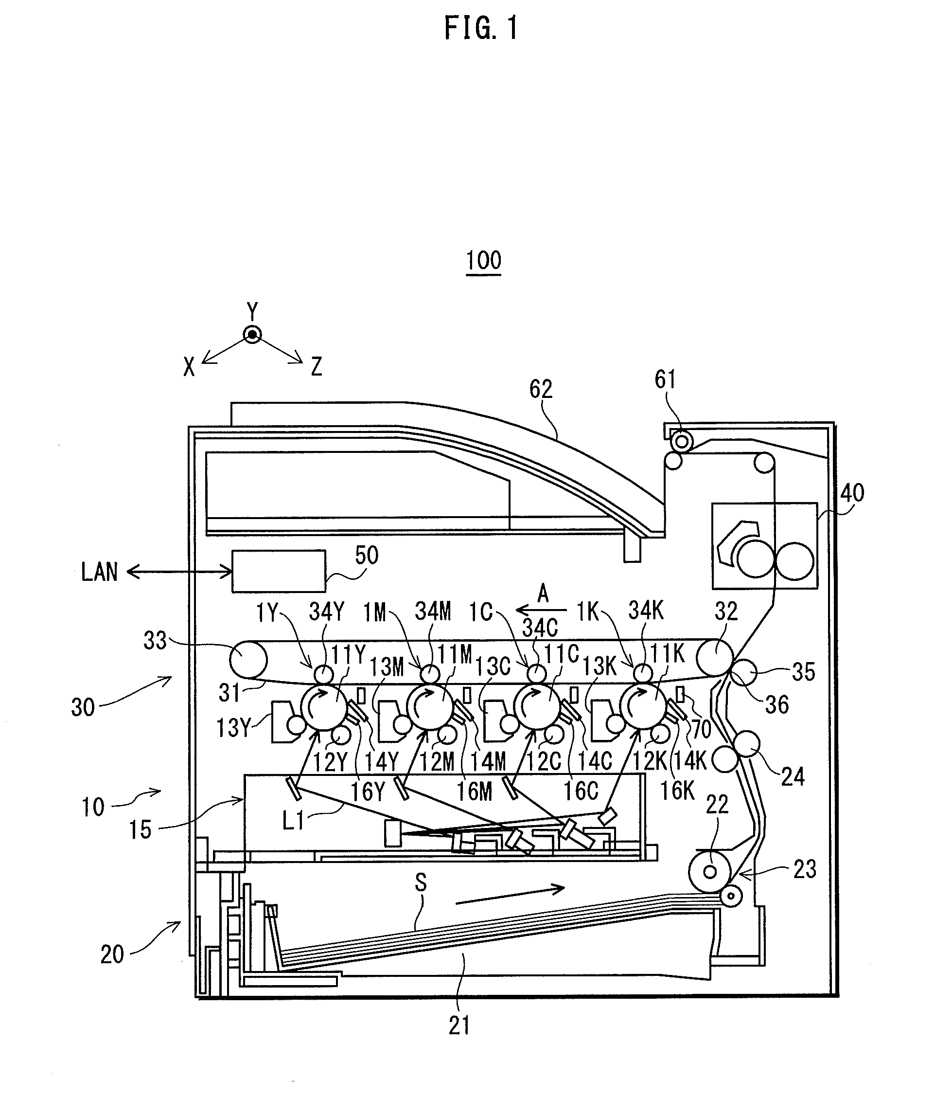
[0041]FIG. 1 is a schematic diagram showing an overall structure of a printer 100 pertaining to the present embodiment. The printer 100 is configured to include an image former 10, a paper feeder 20, a transfer part 30, a fixing device 40, a controller 50, and the like.

[0042]The printer 100 is connected to a network (e.g. LAN: Local Area Network). Upon receiving a print job execution instruction from an external terminal apparatus (not shown), the printer 100 executes full-color image formation, in accordance with the instruction, by forming toner images respectively of colors cyan, magenta, yellow, and black, and transferring the formed toner images by multiple transfer.

[0043]The cyan, magenta, yellow, and black reproduction colors are represented as C, M, Y, and K respectively in this specification, and the letters C, M, Y, and K are appended to numbers pertaining to the reproduction colors.

[0044]The image former 10 includes image forming units 1C,...

second embodiment

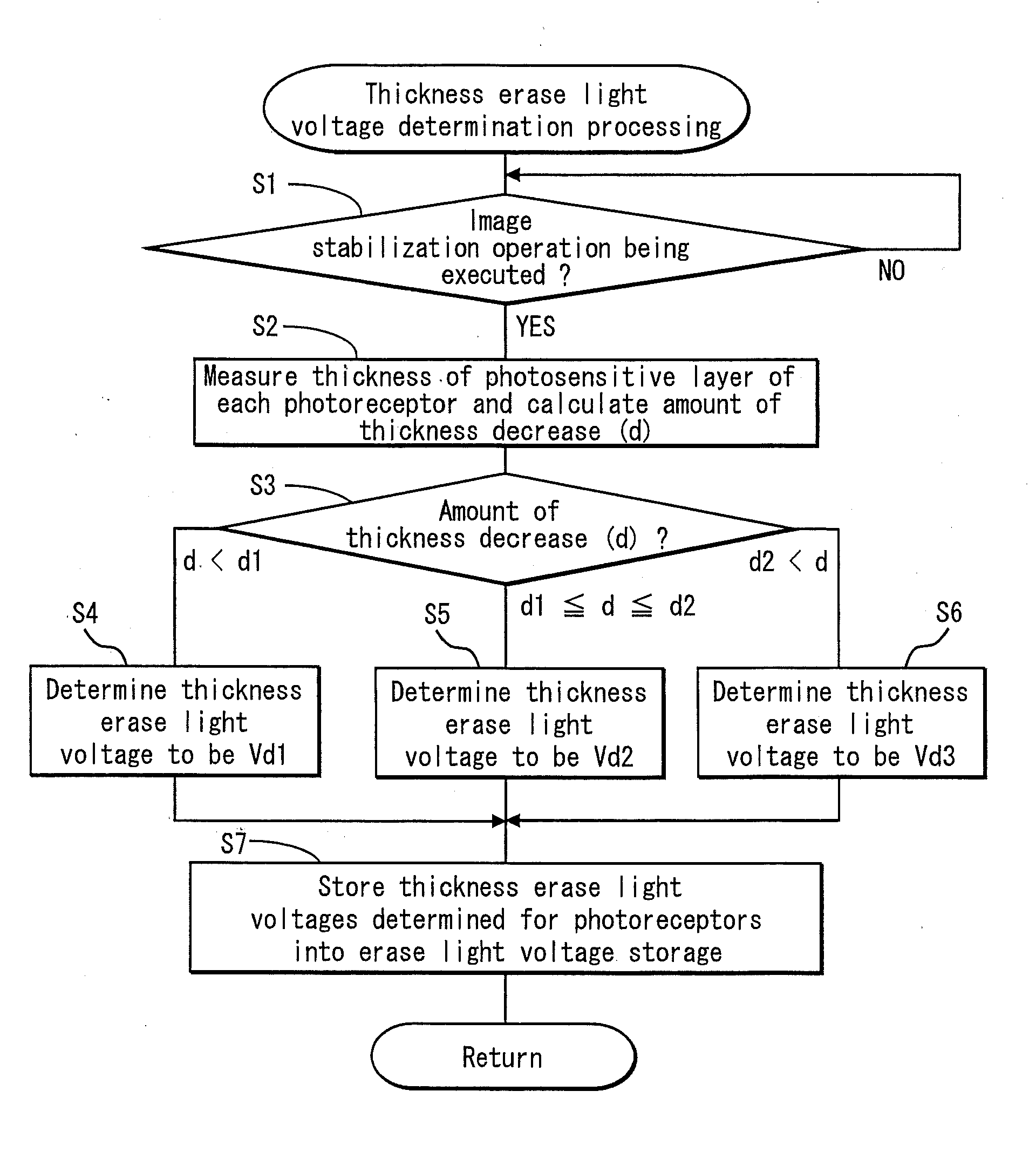
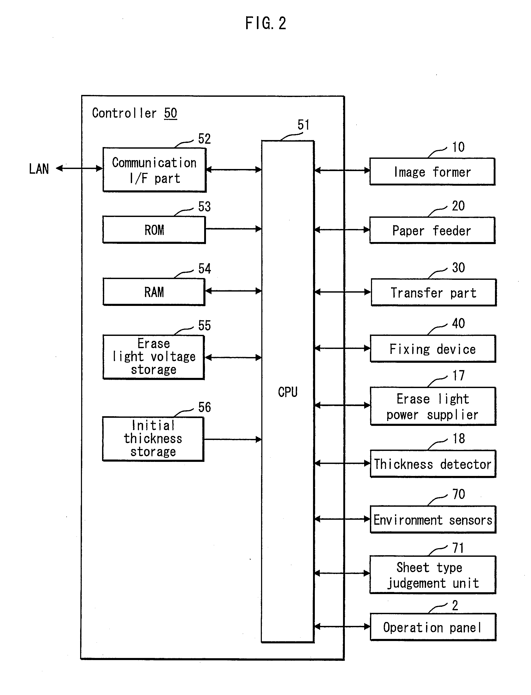
[0084]The first embodiment has described a structure in which the thickness of the photosensitive layer of each photosensitive drum is measured, and the amount of erase light to be emitted is changed in accordance with the amount of thickness decrease of the photosensitive layer of each photosensitive drum. On the other hand, according to the present embodiment, an environment sensor is provided in a vicinity of each photosensitive drum, and the amount of erase light to be emitted to each photosensitive drum is individually changed based on information on the absolute humidity obtained from a detection result of the corresponding environment sensor, in addition to the amount of thickness decrease. Note that in order to avoid explanatory repetition, explanation on the same content as the first embodiment is omitted, and the same components are assigned the same reference numerals.

2-1. Control on Amount of Erase Light Based on Temperature and Humidity

[0085]Environment sensors 70C, 70M...

third embodiment

3-1. Control of Amount of Erase Light Based on Color of Toner

[0102]The photoreceptor memory occurs due to electric charge remaining on the photosensitive drum 11 after a transfer. However, noticeability of the image deterioration differs depending on the color of the toner even if the amount of remaining electric charge is the same. Accordingly, the resulting image deterioration varies in degree as well. In the present embodiment, explanation is given on a structure that changes the amount of erase light depending on the color of the toner provided to the photosensitive drum 11. Note that in order to avoid explanatory repetition, explanation on the same content as the first embodiment is omitted, and the same components are assigned the same reference numerals.

[0103]Image deterioration due to the photoreceptor memory varies in degree of noticeability even if the electric intensity of the photoreceptor memory is the same. For example, the Y-color (yellow) is not very noticeable, whil...


PUM


Abstract

Electric charge remaining on a photoreceptor after transfer causes image deterioration. According to one conventional method widely used in view of this problem, erase light is emitted onto a photoreceptor after the transfer to remove the electric charge remaining on the photoreceptor. However, such a method poses the following problem: emission of erase light leads to light-induced fatigue of the photoreceptor, and as a result, the photoreceptor which has deteriorated from the light-induced fatigue wears down due to abrasion and the like with a cleaner blade, resulting in a shorter lifetime of the photoreceptor. Thus, the thickness of the photosensitive layer is detected to acquire the amount of thickness decrease, and the amount of the erase light is reduced according to the acquired amount of thickness decrease.

Description

[0001]This application is based on application No. 2009-065535 filed in Japan, the content of which is hereby incorporated by references.BACKGROUND OF THE INVENTION[0002](1) Field of the Invention[0003]The present invention relates to an image forming apparatus, and in particular to a technique to reduce deterioration of a photoreceptor due to light-induced fatigue while also maintaining an image quality by neutralizing and erasing electric charge remaining on the photoreceptor by emitting erase light prior to charging.[0004](2) Description of the Related Art[0005]Image forming apparatuses using an electrophotographic system charge a surface of a photoreceptor to a uniform electric potential with use of a charger, forms a latent image by exposure scanning using a laser beam, develops the latent image using toner, and transfers the developed toner image onto a recording sheet.[0006]However, when the toner image formed on the photoreceptor is transferred, the following phenomenon occu...

Claims


Application Information

Patent Timeline
IPC IPC(8): G03G15/04
CPCG03G21/08
Inventor INOUE, KEISUKE
Owner KONICA MINOLTA BUSINESS TECH INC
Why Eureka
Try Eureka