Solid electrolyte membrane, method and apparatus for producing the same, membrane electrode assembly and fuel cell

a solid electrolyte membrane and fuel cell technology, applied in the direction of conductors, sustainable manufacturing/processing, final product manufacturing, etc., can solve the problems of low power density and durability of fuel cells, denatured polymers, and insufficient electromotive force of fuel cells using solid electrolyte membranes, etc., to achieve excellent electromotive force and high and uniform proton conductivity

Inactive Publication Date: 2010-09-23
FUJIFILM CORP
View PDF3 Cites 59 Cited by
  • Summary
  • Abstract
  • Description
  • Claims
  • Application Information

AI Technical Summary

Benefits of technology

[0039]According to the present invention, the solid electrolyte membrane having high and uniform proton conductivity is mass-produced continuously. When the membrane electrode assembly using the solid electrolyte membrane of the present invention is used in the fuel cell, the fuel cell exerts excellent electromotive force.

Problems solved by technology

However, a polymer is denatured due to heating, and impurities in the polymer material remain in the membrane.
When a solid electrolyte membrane containing the organic solvent is used for a fuel cell, the organic solvent may flow inside the fuel cell, and it will lower power density and durability of the fuel cell.
As a result, the fuel cell using such solid electrolyte membrane cannot exert enough electromotive force.
Therefore, it usually takes more than 20 hours to completely dry the casting membrane or the wet membrane.
Therefore, the total producing time of the solid electrolyte membrane becomes extremely long.
Such long drying time may cause various problems in a continuous line production.
In addition, it takes time to investigate the cause or to respond when any problems occur in the line.
According to such methods alone, however, the wet membrane will have drying unevenness on its surface or inside thereof, and therefore the quality and the appearance of the obtained solid electrolyte membrane often become uneven.
Occurrence of pinholes, which are localized holes, is an example of the unevenness of the quality and the appearance of the membrane.
According to this method, however, the casting membrane cannot obtain enough self-supporting property, and therefore the casting membrane cannot be easily peeled off.
However, concrete methods are not disclosed.
Moreover, Japanese Patent Laid-Open Publication Nos. 2005-268144 and 2005-268145 do not disclose or suggest any concrete methods of large scale manufactures or continuous productions of the membrane.
The method disclosed in Japanese Patent Laid-Open Publication No. 2004-079378 has a problem in that micropores are formed on the membrane by immersing the membrane in the water.
As a result, the uniform membrane cannot be obtained.
The methods disclosed in Japanese Patent Laid-Open Publication Nos. 2005-232240, 2005-235466 and 2005-146018 do not give any solutions for difficulty of removing the organic solvent having high boiling point from the membrane by drying.
Therefore, the methods according to these references take extremely long time for drying the membrane, and it results in decreasing the productivity.
However, these references do not particularly disclose the drying.

Method used


Image

  • Solid electrolyte membrane, method and apparatus for producing the same, membrane electrode assembly and fuel cell
  • Solid electrolyte membrane, method and apparatus for producing the same, membrane electrode assembly and fuel cell
  • Solid electrolyte membrane, method and apparatus for producing the same, membrane electrode assembly and fuel cell

Examples


example 1

[0379]Next, Examples of the present invention are described.

[0380]A compound whose X in the chemical formula 1 was cation species other than a hydrogen atom H was used as the precursor. This precursor is referred to as a material A. In the material A, composition in the chemical formula 1 was as follows: X was Na, Y was SO2, n was 0.33, m was 0.67, Z was (I) of the chemical formula 2, the number average molecular weight Mn was 61000, and the weight average molecular weight Mw was 159000. The solvent was a mixture of solvent components 1 and 2 shown below. The solvent component 1 was a good solvent of the material A, and the solvent component 2 was a poor solvent of the material A. The material A and the solvent were mixed by the following composition to dissolve the material A in the solvent. Thus, a dope with the material A of 20 wt. % to the total weight thereof was formed. Hereinafter this dope is referred to as a dope A.

Material A100 pts. wtSolvent component 1: DMSO256 pts. wtSo...

example 2

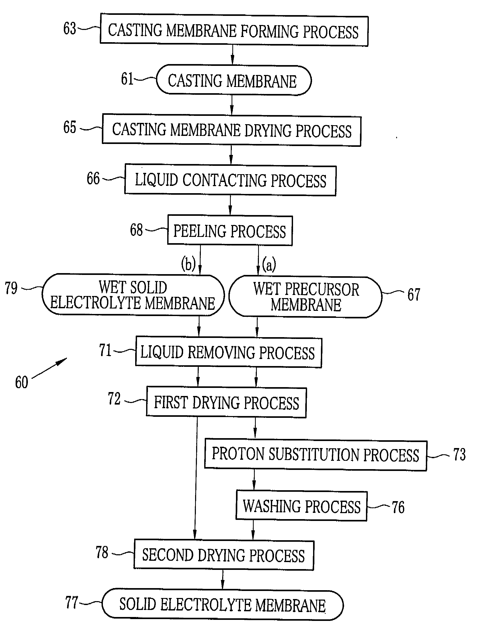
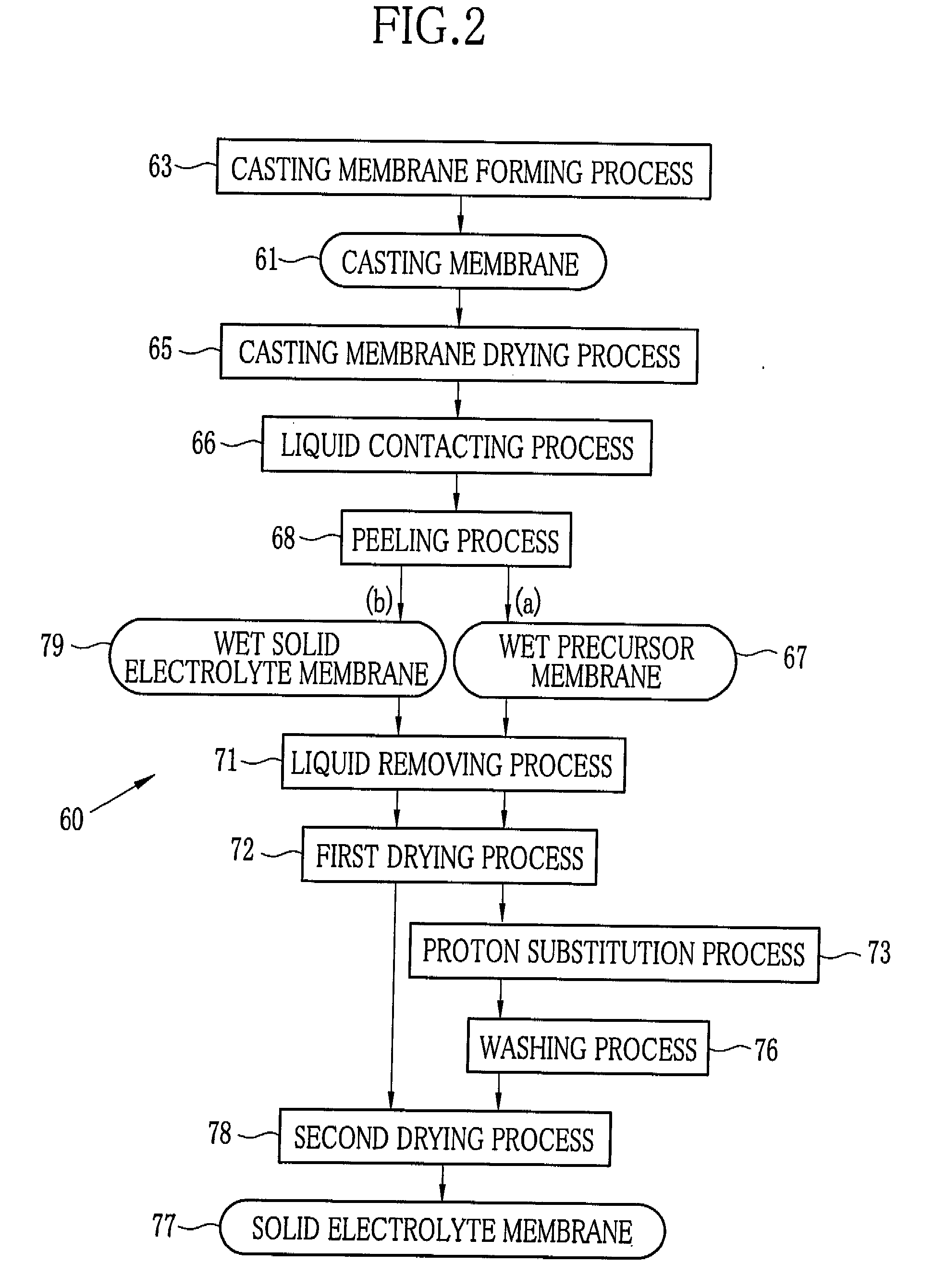
[0383]The material A in the Example 1 was replaced by a material B, and a dope was produced by the following composition. Time for applying the dry air to any part of the casting membrane 61 by the casting membrane drying devices 81 was 20 minutes in a row. The time was determined such that the casting membrane 61 included 185 pts.wt of DMSO and 10 pts.wt of methanol to 100 pts.wt of the material B at a time of starting the liquid contacting process 66. Other conditions were same as those of the Example 1. In the material B, composition in the chemical formula 1 was as follows: X was Na, Y was SO2, Z was a mixture of (I) and (II) of the chemical formula 2, n was 0.33, m was 0.67, the number average molecular weight Mn was 68000, and the weight average molecular weight Mw was 200000. In the chemical formula 2, (I) was 0.7 mol %, (II) was 0.3 mol %. The solvent was a mixture of solvent components 1 and 2 shown below. The solvent component 1 was a good solvent of the material B, and th...

example 3

[0384]Time for applying the dry air to any part of the casting membrane 61 by the casting membrane drying devices 81 was 5 minutes in a row. The time was determined such that the casting membrane 61 included 195 pts.wt of DMSO and 100 pts.wt of methanol to 100 pts.wt of the material B at a time of starting the liquid contacting process 66. Other conditions were same as those of the Example 2.


PUM


Abstract

A dope (24) containing a solvent and a precursor of a solid electrolyte is cast onto a belt (94) to form a casting membrane (61). The casting membrane (61) is immersed in a contact liquid (100) in a liquid bath (83) and peeled as a wet precursor membrane (67) from the belt (94) when having a self-supporting property. The solvent contained in the wet precursor membrane (67) is substituted by the contact liquid (100), and the wet precursor membrane (67) is transported out of the liquid bath (83). After being dried in a tenter device (85), the wet precursor membrane (67) is contacted with a proton solution (110) in a proton substitution chamber (86) to perform proton substitution to the precursor contained in the wet precursor membrane (67), and then dried in a drying chamber (87) to be a solid electrolyte membrane (77).

Description

TECHNICAL FIELD[0001]The present invention relates to a solid electrolyte membrane, a method and an apparatus for producing the same, membrane electrode assembly and a fuel cell using the solid electrolyte membrane, in particular, the present invention relates to a solid electrolyte membrane having excellent proton conductivity used for the fuel cell, a method and an apparatus for producing the same, membrane electrode assembly and a fuel cell using the solid electrolyte membrane.BACKGROUND ART[0002]A fuel cell is actively studied as a next-generation way of generating electricity which can help solving the environmental pollution problems and energy problems. The fuel cell has layered cells (also referred to as membrane electrode assembly (MEA)), and the cells are electrically connected in series. The MEA includes an anode and a cathode which are connected through an external circuit, and a solid electrolyte membrane interposed between the anode and the cathode. A major example of ...

Claims


Application Information

Patent Timeline
Patent Type & Authority Applications(United States)
IPC IPC(8): H01M8/10B29C41/50H01M8/1027H01M8/1032H01M8/1039H01M8/1081
CPCB29C41/28H01B1/122H01M8/1027H01M8/1032Y02E60/522H01M8/1081H01M2300/0082Y02E60/523H01M8/1039Y02P70/50Y02E60/50
Inventor MIYACHI, HIROSHITAKEDA, RYO
Owner FUJIFILM CORP
Why Eureka
Try Eureka