Separator for fuel cell and fuel cell

a technology of separator and fuel cell, which is applied in the direction of fuel cells, fuel cell details, electrical apparatus, etc., can solve problems such as restricting potential, and achieve the effects of increasing the contact resistance of the gas separator, preventing deformation of the separator, and strengthening the rigidity of the separator

Active Publication Date: 2010-09-23
TOYOTA JIDOSHA KK
View PDF1 Cites 13 Cited by
  • Summary
  • Abstract
  • Description
  • Claims
  • Application Information

AI Technical Summary

Benefits of technology

[0014]In the gas separator for the fuel cell according to the second aspect of the invention, the reinforcing element is provided along the parting linear convex. The presence of the reinforcing element effectively enhances the rigidity of the separator at a location close to the parting linear convex and thereby prevents deformation of the separator. This arrangement desirably avoids an increase of the contact resistance of the gas separator against an adjacent member. The presence of the reinforcing element effectively prevents the fluid flow from going over the parting linear convex or a path short cut of the fluid flow on the one side, thus avoiding a decrease of the utilization rate of the fluid. In the gas separator of the second aspect, the reinforcing element is formed and protruded on the other side, which is opposite to the one side with the p

Problems solved by technology

This arrangement desirably restricts the potential effect of the pre

Method used


Image

  • Separator for fuel cell and fuel cell
  • Separator for fuel cell and fuel cell
  • Separator for fuel cell and fuel cell

Examples


second embodiment

B. Second Embodiment

[0066]In the structure of the first embodiment, the reinforcing elements 47 are formed as the salients protruded on the refrigerant flow path side. Reinforcing elements may alternatively be formed as salients protruded on the gas flow path side. This modified structure is described below as a second embodiment. A fuel cell of the second embodiment has the same structure as that of the fuel cell of the first embodiment, except that the reparatory 15 is replaced with a separator 115. The like components of the second embodiment to those of the first embodiment are expressed by the like numerals and are not specifically explained here.

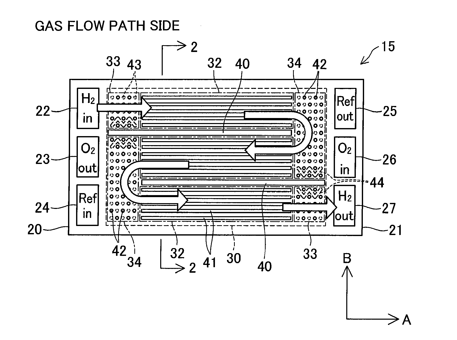
[0067]FIG. 9 is plan views showing the structure of the separator 115 included in the fuel cell of the second embodiment. FIG. 9(A) shows a gas flow path side, and FIG. 9(B) shows a refrigerant flow path side. The separator 115 has the same structure as that of the separator 15, except that the reinforcing elements 47 are replaced by r...

modified example 1

C1. Modified Example 1

[0070]In the first and the second embodiments, the reinforcing elements 47 and 147 are formed as the zigzag-shaped linear convexes with bends. This shape is, however, neither restrictive nor essential. Each of the reinforcing elements may be formed as a straight linear convex with no bends according to the arrangement of the projections 42 and 46 provided in the inflow outflow areas 33 and in the connection areas 34. One exemplary structure of such modification is shown as a first modified example in FIG. 10. The like components of the first modified example to those of the first embodiment are expressed by the like numerals and are not specifically explained here. FIG. 10 is an enlarged plan view showing a partial area of the refrigerant flow path side of the separator corresponding to the location in the vicinity of the parting linear convex 40. In the first modified example shown in FIG. 10, each of straight linear reinforcing elements 247 is formed by conne...

modified example 2

C2. Modified Example 2

[0071]In the first and the second embodiments, a single reinforcing element is formed on each side of and along each of the parting linear convexes 40 by connecting the positions where the projections 46 are expected to be formed according to the regularity of the intervals of the projections 46. In one modification, multiple convexes may be formed by discretely connecting certain positions where the projections 46 are expected to be formed and may constitute as a whole a reinforcing element arranged along each of the parting linear convexes 40. One exemplary structure of such modification is shown as a second modified example in FIG. 11. The like components of the second modified example to those of the first embodiment are expressed by the like numerals and are not specifically explained here. Like the illustration of FIG. 10, FIG. 11 is an enlarged plan view showing a partial area of the refrigerant flow path side of the separator corresponding to the locati...


PUM


Abstract

A separator has a concavo-convex structure formed in mutually reversed shapes on two opposite sides thereof to define flow paths of different fluids on the respective two sides. The concavo-convex structure includes multiple first projections formed and protruded on one side of the two opposite sides and arranged at intervals having a preset regularity. The concavo-convex structure also includes multiple second projections formed and protruded on the other side of the two opposite sides in a specific area corresponding to an area for formation of the multiple first projections on the one side and arranged at intervals having a preset regularity. The concavo-convex structure further includes reinforcing elements protruded on the one side. Each of the reinforcing elements is formed as a convex in a specific shape of connecting multiple positions where the first projections are expected to be formed according to the preset regularity, while avoiding positions corresponding to the second projections formed on the other side. This arrangement effectively prevents a potential trouble caused by deformation of the separator due to a pressure difference between the flow pressures of the respective fluids flowing on the respective sides of the separator.

Description

TECHNICAL FIELD[0001]The present invention relates to a fuel cell and a separator for the fuel cell.BACKGROUND ART[0002]One known configuration of a separator used for fuel cells has a concavo-convex structure formed in mutually reversed shapes on two opposite sides thereof and define flow paths of different fluids on the respective sides (see, for example, Japanese Patent Laid-Open No. 2003-142126). In a fuel cell assembly including such separators, the concavo-convex structures formed on opposed sides of adjacent separators are arranged to side each other. The convexes of the concavo-convex structures formed on the opposed sides of the adjacent separators mutually support the adjacent separators. This assures the sufficient rigidity of the whole fuel cell assembly. The relevant prior art techniques include those disclosed in, for example, Japanese Patent Application No. 2006-519715 (International Publication No. 06 / 075786) and Japanese Patent Laid-Open No. 2005-108505.[0003]In a s...

Claims


Application Information

Patent Timeline
IPC IPC(8): H01M8/02
CPCH01M8/0254Y02E60/50H01M2008/1095H01M8/0258H01M8/0267H01M8/241H01M8/2457H01M8/2483
Inventor YAMAMOTO, YOSHINORINAKAJI, HIROYAHAMADA, HITOSHISUZUKI, TOSHIYUKIAONO, HARUYUKI
Owner TOYOTA JIDOSHA KK
Why Eureka
Try Eureka