Electronic analyte assaying device

a technology of assaying device and analyte, which is applied in the direction of measurement device, instruments, scientific instruments, etc., can solve the problems of invalid test results, single-step devices, and obviation of performing, so as to achieve the effect of avoiding the necessity of performing

Active Publication Date: 2010-09-23
CHURCH & DWIGHT CO INC
View PDF67 Cites 61 Cited by
  • Summary
  • Abstract
  • Description
  • Claims
  • Application Information

AI Technical Summary

Problems solved by technology

Single-step devices, therefore, obviate the necessity of performing, subsequent to the application of the sample, a series of manipulations which may be time consuming and / or may introduce errors in the end result.
It has been found, however, that invalid test results may arise from the use of single-step devices, particularly devices wherein the fluid sample is applied directly from a fluid stream through a urine inlet port defined by the casing onto assay material enclosed therein.

Method used


Image

  • Electronic analyte assaying device
  • Electronic analyte assaying device
  • Electronic analyte assaying device

Examples


Embodiment Construction

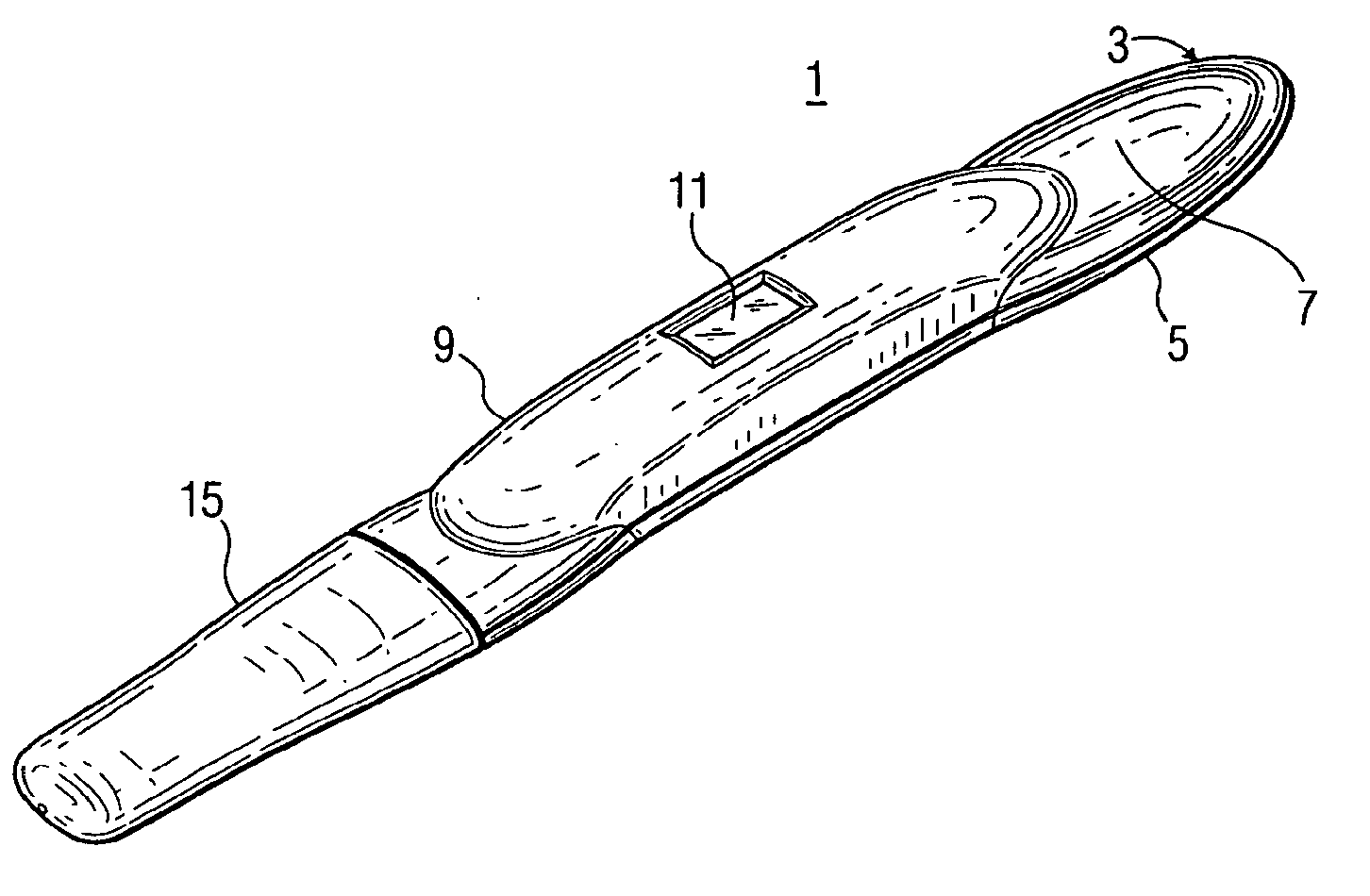
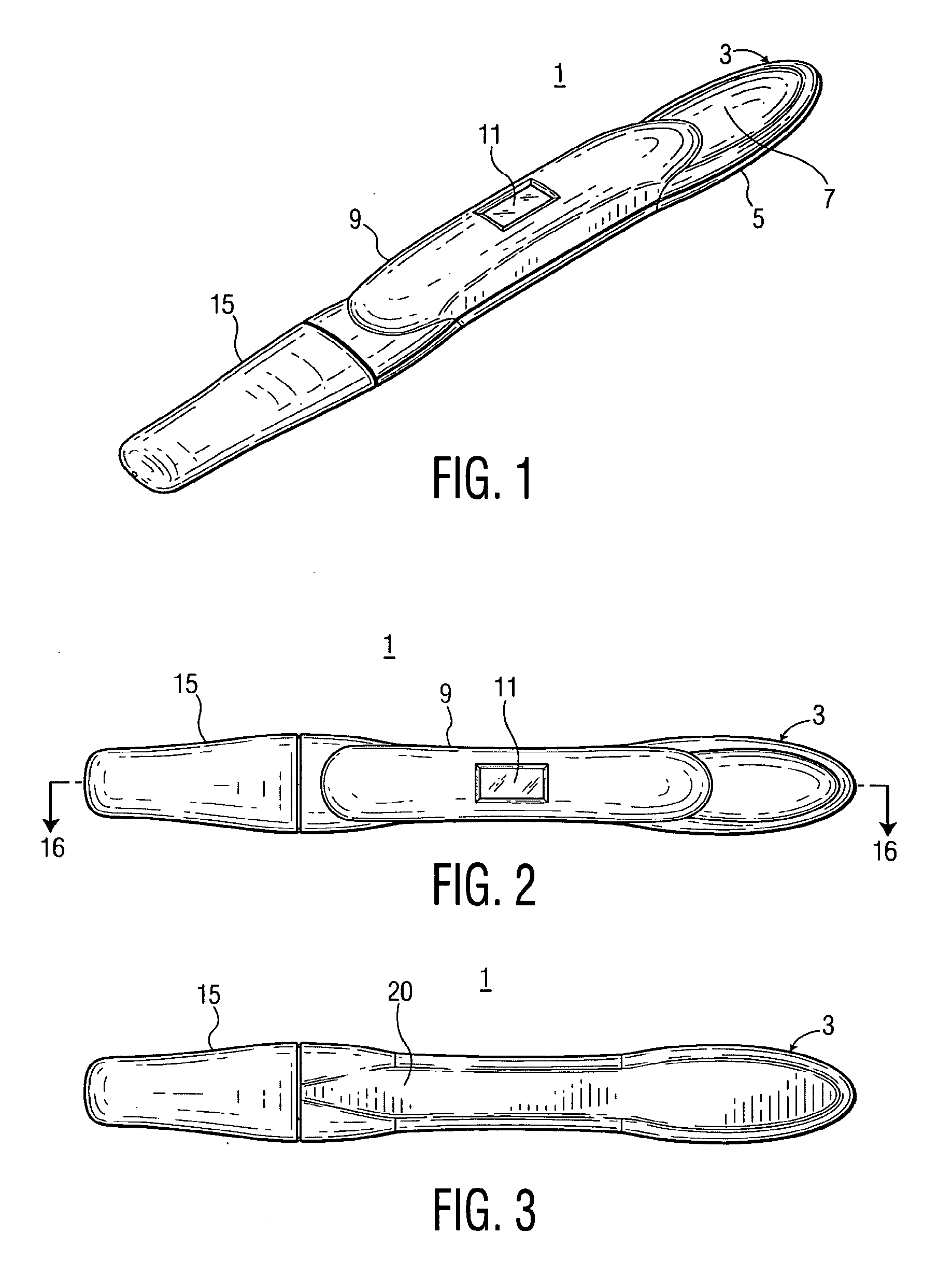
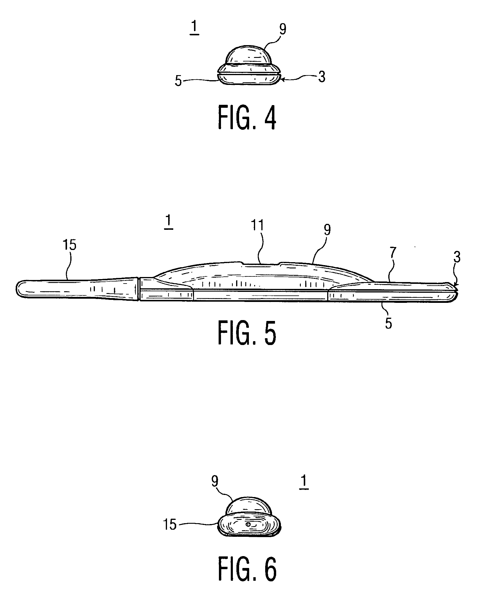
[0049]The present invention provides electro-optical processing in an improved single-step device for detecting a preselected analyte in a urine stream. With reference to FIGS. 1 through 7, in one embodiment of the present invention, the device 1 includes a casing 3 that has a front portion 5 configured to provide a top recessed portion 7 shaped to permit a user to place their thumb into the recessed portion 7 and their forefinger on the bottom of the front portion 5 to securely hold the device 1. A raised more central portion 9 of the case 3 includes a centrally located window 11 to permit a user to observe test results provided on an underlying LCD display 13 (see FIG. 8). A removable cap 15 is provided at the other end of the device 1. In one embodiment, the device 1 with the cap 15 installed on the casing 3 is about 5.7 inches long, the cap 15 being about 1.5 inches long. The central portion 9 of casing 3 is about 1.5 inches long, in this example. The dimensions are not meant to...


PUM


Abstract

The invention is an electronically processed single-step test device for detecting the presence of a preselected analyte in a fluid. The device includes a hollow rectangular outer casing, disposed within co-joined upper and lower sections of the casing are assay material, an electronic processing system, and a LCD display. The LCD display is observable through a viewing window. The assay material is a sorptive material including a fluid sample application region in the form of a sample wick in fluid communication with a test strip. The test strip includes an analyte capture region adjacent to a light shield. The electronic processing system includes red and green LEDs which are alternately pulsed or energized over predetermined periods of time to determine if fluid test results show a marker or markers in the capture region indicative of the presence of a preselected analyte in the fluid. If so, Yes+ is displayed on the LCD. If not, No− is displayed on the LCD.

Description

RELATED APPLICATIONS AND PATENTS[0001]The present invention is related to U.S. Pat. No. 5,739,041, entitled “IMPROVED DIAGNOSTIC DETECTION DEVICE”; and to U.S. Pat. No. 6,319,676, entitled “DIAGNOSTIC DEVICE AND METHOD”; and to U.S. Pat. No. 5,846,835, entitled “MANUFACTURING METHOD FOR LAMINATED IMMUNODIAGNOSTIC TEST DEVICE”; and to Design U.S. Pat. No. Des. 390,667, entitled “DIAGNOSTIC DETECTION DEVICE”; and to U.S. Pat. No. 6,046,057, entitled “ANALYTE ASSAYING DEVICE”; and to U.S. Pat. No. 6,277,650, entitled “ANALYTE ASSAYING DEVICE”; and to Design application Ser. No. 29 / 174,065, entitled ELECTRONIC DIAGNOSTIC DETECTION DEVICE CASING WITH REMOVABLE CAP, filed Jan. 10, 2003; all of which are incorporated herein in their entirety to the extent that they do not conflict herewith. These related applications and patents are all assigned to the same Assignee as the present invention.FIELD OF THE INVENTION[0002]This invention relates to an improved device for assaying a preselected ...

Claims


Application Information

Patent Timeline
Patent Type & Authority Applications(United States)
IPC IPC(8): G01N33/53G01N30/00
CPCG01N21/8483G01N33/54373G01N33/5302G01N33/689G01N33/558
Inventor NAZARETH, ALBERT R.DELAHANTY, FRANCIS T.BANDRU, GREGORY M.WIECK, HENRY J.SYNAKOWSKI, STEPHEN R.
Owner CHURCH & DWIGHT CO INC
Why Eureka
Try Eureka