
Arrangement for improving accuracy of pressure measurement and flow sensor

a technology of flow sensor and pressure measurement, which is applied in the field of arrangement for improving the accuracy of pressure measurement and flow sensor, can solve the problems of high accuracy of flow sensor, high cost, and high cost, and achieve the effect of improving the accuracy of flow measuremen

Active Publication Date: 2010-09-30
GENERAL ELECTRIC CO
View PDF11 Cites 27 Cited by
  • Summary
  • Abstract
  • Description
  • Claims
  • Application Information

AI Technical Summary

Benefits of technology

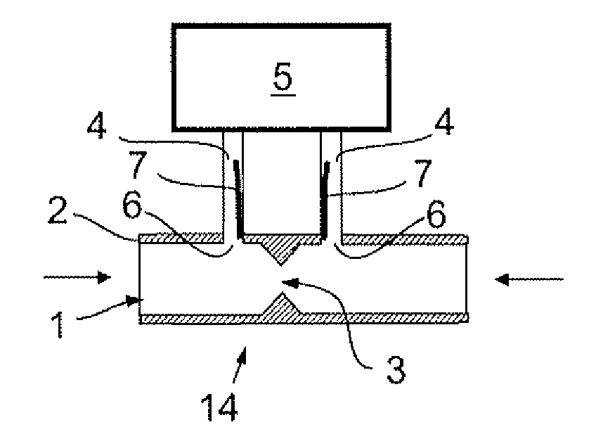
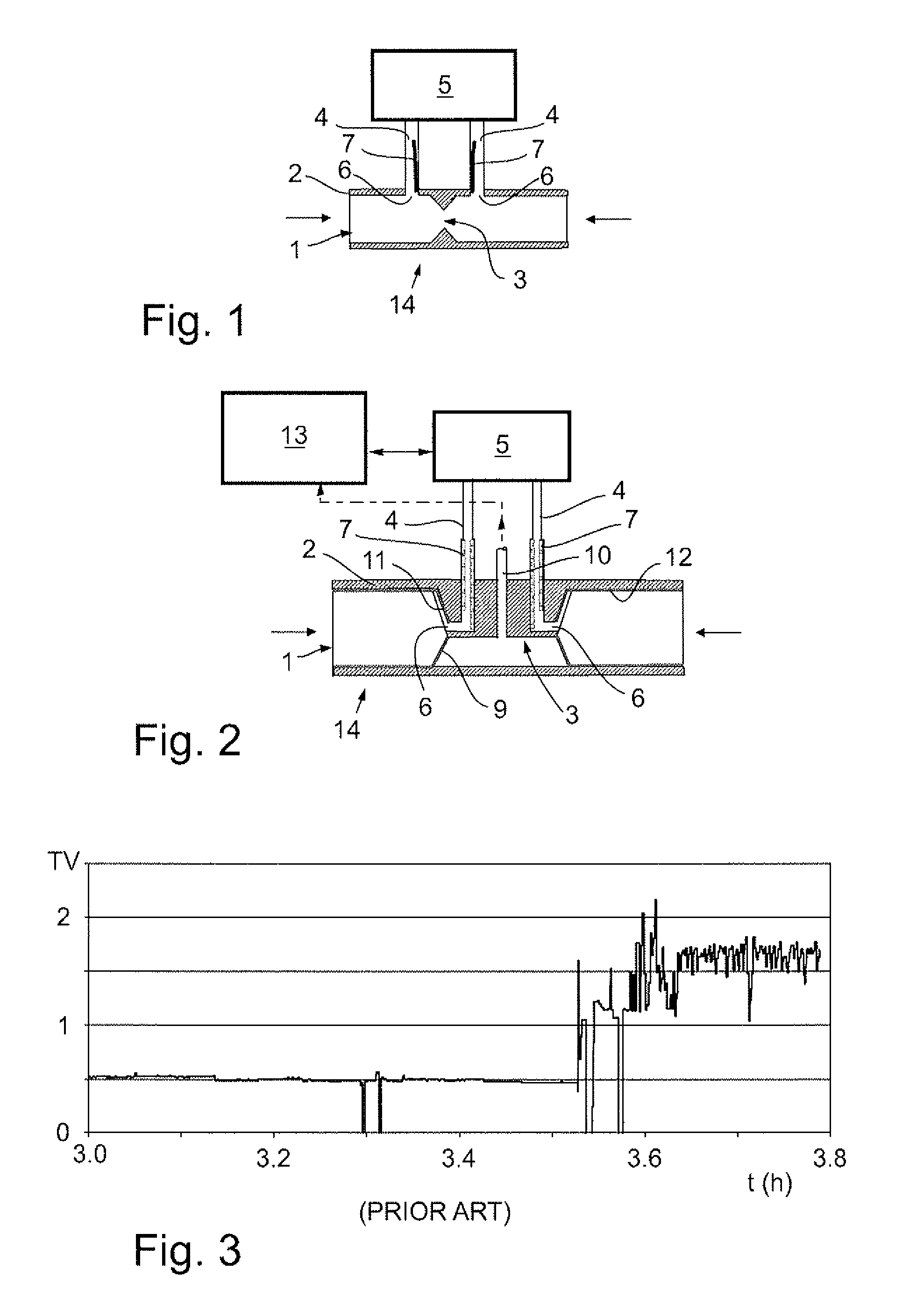
[0008]In an embodiment, an arrangement for improving an accuracy of a pressure measurement made of a breathing gas including drops of water or humidity flowing along a flow channel includes at least one pressure measuring channel configured to transmit a pressure of the breathing gas flowing along the flow channel to a measuring device to make the pressure measurement. The pressure measuring channel is equipped with a capillary material enabling capillary suctioning of water.
[0009]In another embodiment, an arrangement for improving an accuracy of a pressure measurement made of a flowing breathing gas with drops of water or humidity includes a flow channel along which the breathing gas is flowing and a restricting element in the flow channel for the differential pressure measurement. The arrangement for improving the an accuracy of a pressure measurement made of a flowing breathing gas with drops of water or humidity also includes at least two pressure measuring channels, one of the two pressure measuring channels being connected to one side of the restricting element and another of the two pressure measuring channels being connected to another side of the restricting element, the two pressure measuring channels transmitting pressure signals of the breathing gas on both sides of the restricting element to a measuring device to make the differential pressure measurement. At least one of the pressure measuring channels is equipped with a capillary material enabling capillary suctioning of water.
[0010]In yet another embodiment a flow sensor for a flow rate measurement of a breathing gas including drops of water or humidity includes a flow channel along which the breathing gas is flowing and a restricting element in the flow channel for the differential pressure measurement. The flow sensor for a flow rate measurement of a breathing gas including drops of water or humidity also includes at least two pressure measuring channels, one of the two pressure measuring channels being connected to one side of the restricting element and another of the two pressure measuring channels being connected to another side of the restricting element, the two pressure measuring channels transmitting pressure signals of the breathing gas on both sides of the restricting element to a measuring device to make the flow rate measurement. At least one of the pressure measuring channels is equipped with a capillary material enabling capillary suctioning of water for improving an accuracy of the flow rate measurement.

Problems solved by technology

However, measurements under clinical conditions involve many problems.
It is clear that such soiling is likely to affect the operation of most types of flow sensors.
This problem with a drifting signal can be severe especially when using the flow sensor under very humid conditions typically for several hours.
However, this method requires a heating element and electrical connectors.
However, there is also a problem with the pressure measuring tubes connecting the differential pressure orifices in the flow path with the differential pressure sensor.
If the water clogs either one of those tubes there will be a fast change in the pressure difference to a new level, which is incorrect.
One remedy is to heat the orifices and tube entrances, but this method is not customer friendly as mentioned above.
This may work in many cases, but under very wet conditions like prolonged use in critical care, water may still enter the pressure measuring tubes and cause erroneous signal levels.
Even if no water then can enter the pressure measuring tubes the membrane will cause a pressure drop which may not be constant under very wet conditions or when the membrane gets soiled with mucus.
This would induce an error in the measured flow value.
This method mostly works but it is technically a more complicated and also expensive construction.
Further, it could contaminate the respiratory tube.

Method used


Image

  • Arrangement for improving accuracy of pressure measurement and flow sensor
  • Arrangement for improving accuracy of pressure measurement and flow sensor
  • Arrangement for improving accuracy of pressure measurement and flow sensor

Examples


Embodiment Construction

[0016]Specific embodiments are explained in the following detailed description making a reference to accompanying drawings. These detailed embodiments can naturally be modified and should not limit the scope of the invention as set forth in the claims.

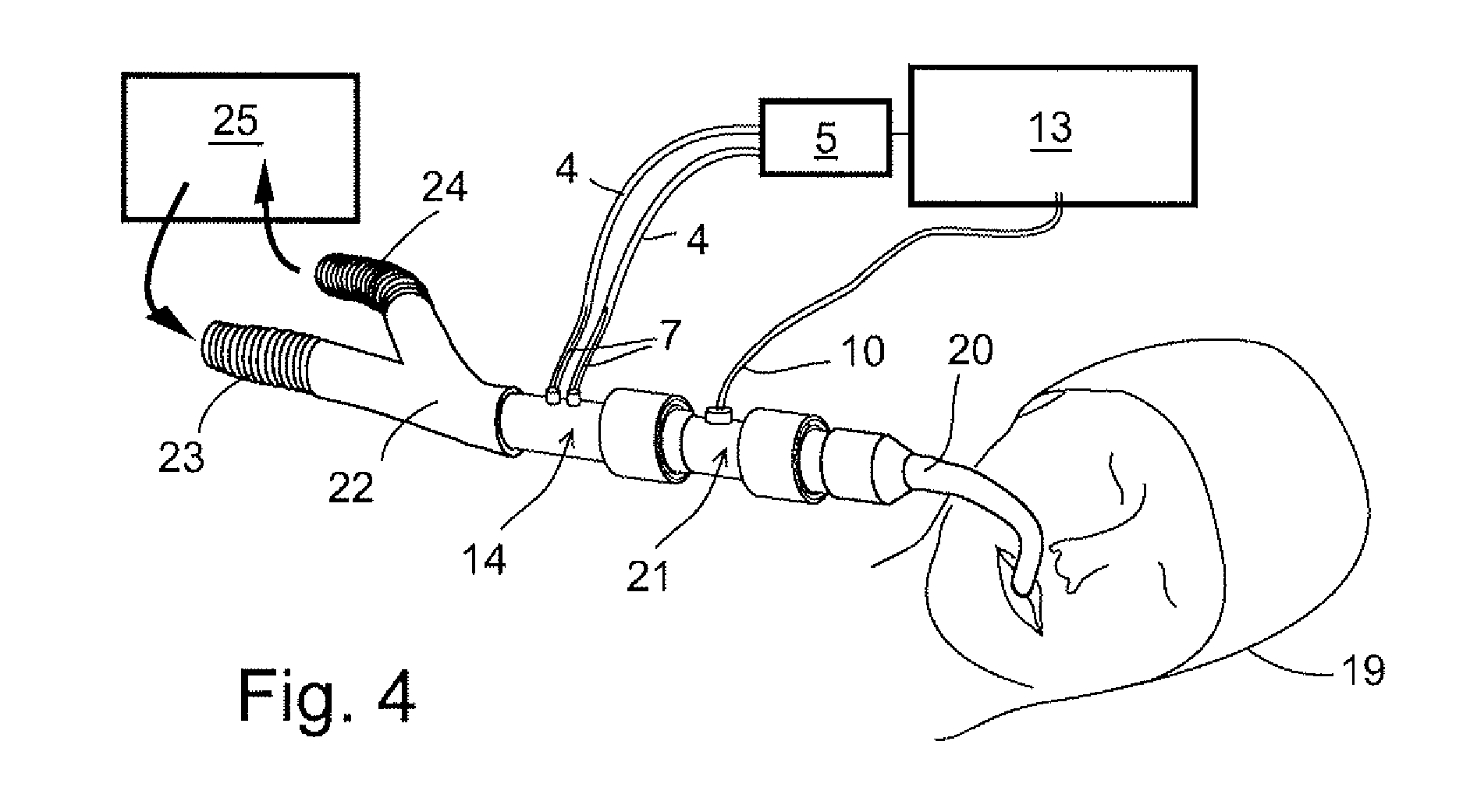
[0017]FIGS. 1 and 2 present different types of arrangements for improving an accuracy of a pressure measurement, especially a breathing gas pressure measurement, either can be measured an absolute pressure or a differential pressure. The differential pressure of a gas flow can be measured over a flow restriction indicating a flow rate. The arrangement for measuring the differential pressure can include a separate flow sensor or the flow sensor is an integral part of a channel conveying a breathing gas. The flow sensors can also be used to measure the absolute pressure, in which case the breathing gas pressure is compared to outside pressure.

[0018]The flow sensors 14 presented in FIGS. 1 and 2 comprise a flow channel 1 for conveying a g...


PUM


Abstract

An arrangement for improving an accuracy of a pressure measurement made of a breathing gas including drops of water or humidity flowing along a flow channel is disclosed herein. The arrangement includes at least one pressure measuring channel to transmit a pressure of the breathing gas flowing along the flow channel to a measuring device to make the pressure measurement. The pressure measuring channel is equipped with a capillary material enabling capillary suctioning of water. Also a flow sensor for a flow rate measurement of a breathing gas including drops of water or humidity is provided.

Description

CROSS-REFERENCE TO RELATED APPLICATIONS[0001]This application claims priority under 35 U.S.C. §§119(a)-(d) or (f) to prior-filed, co-pending European patent application number 09396003.7, filed on Mar. 27, 2009, which is hereby incorporated by reference in its entirety.BACKGROUND OF THE INVENTION[0002]This disclosure relates generally to an arrangement for improving an accuracy of a pressure measurement made of a breathing gas including drops of water or humidity flowing along a flow channel. Also this disclosure relates to a flow sensor for a flow rate measurement of a breathing gas including drops of water or humidity.[0003]In hospitals, during intensive care and operations, a respiratory apparatus must mostly be used to take care of a patient's respiration. An unhindered flow of gases into and out of the patient's lungs is naturally of vital importance. A condition of gas channels can be monitored both by measuring concentrations of inhaled and exhaled gases and by measuring a fl...

Claims


Application Information

Patent Timeline
IPC IPC(8): G01F1/37
CPCA61B5/087A61B5/097A61M16/0808A61M16/0816A61M2016/0027A61M16/0858A61M2016/102A61M2205/7527G01F1/40G01F1/50A61M16/085A61M2016/0036A61M16/0866A61M16/0833
Inventor WECKSTROM, KURT
Owner GENERAL ELECTRIC CO
Learn More