Ionization Pressure Gauge With Bias Voltage And Emission Current Control And Measurement

a technology of ionization pressure gauge and emission current, which is applied in the direction of vacuum gauge using ionisation effects, force measurement, instruments, etc., can solve the problems of high cost and complexity of high-performance servo circuit, affecting cathode bias voltage, and servo control of cathode heating current in hot cathode ionization gauges (hcigs). achieve the effect of facilitating transistor offset measuremen

Active Publication Date: 2017-01-12
MKS INSTR INC
View PDF0 Cites 3 Cited by
  • Summary
  • Abstract
  • Description
  • Claims
  • Application Information

AI Technical Summary

Benefits of technology

[0014]The transistor circuit can include a field effect transistor (FET) that passes the electron emission current. Cathode bias voltage can be equal to a voltage applied to a gate of the FET plus an offset voltage of the FET. The method can include calibrating the transistor circuit by detecting an offset of a transistor in the transistor circuit, and calibrating the transistor circuit can include using a di

Problems solved by technology

Servo control of the cathode heating current in hot cathode ionization gauges (HCIGs) can be problematic for several reasons.
The cost and complexity of a high performance servo circuit can be high.
Moreover, when electron emission current settings are changed, or when pressure in the gauge changes, cathode bias voltage is affected, because electron emission current and cathode bias voltage are coupled (one affects the other) in a traditional instrument design.
Dead time refers to a transient condition in which the filament cathode bias voltage has wandered from the desired nominal value (where the instrument calibration is valid), so pressure measurements are therefore uncalibrated and inaccurate.
Thus, servo control leads to intervals of gauge inaccuracy or unuseability.
Furthermore, the effectiveness of electrical feedthrough insulators can be compromised by conductive contamination that can build up on the feedthrough insulators of ionization gauges such

Method used


Image

  • Ionization Pressure Gauge With Bias Voltage And Emission Current Control And Measurement
  • Ionization Pressure Gauge With Bias Voltage And Emission Current Control And Measurement
  • Ionization Pressure Gauge With Bias Voltage And Emission Current Control And Measurement

Examples


Embodiment Construction

[0026]A description of example embodiments of the invention follows.

[0027]Hot cathode ionization vacuum pressure gauges (HCIGs) are used in a wide variety of applications such as semiconductor manufacturing, thin film deposition, high-energy physics, ion implantation, and space simulation. Many of these applications require high gauge reliability, low failure rates, and good pressure measurement accuracy over many orders of magnitude of pressure. Furthermore, many of these applications require accurate pressure measurements to be repeated at small time intervals and can be intolerant of servo settling times for controlling electron emission current control loop of the HCIG. With these considerations in mind, increasing the capacity of HCIGs to report very accurate pressure measurements at small time intervals without regard to control loop settling and over long lifetimes is very important.

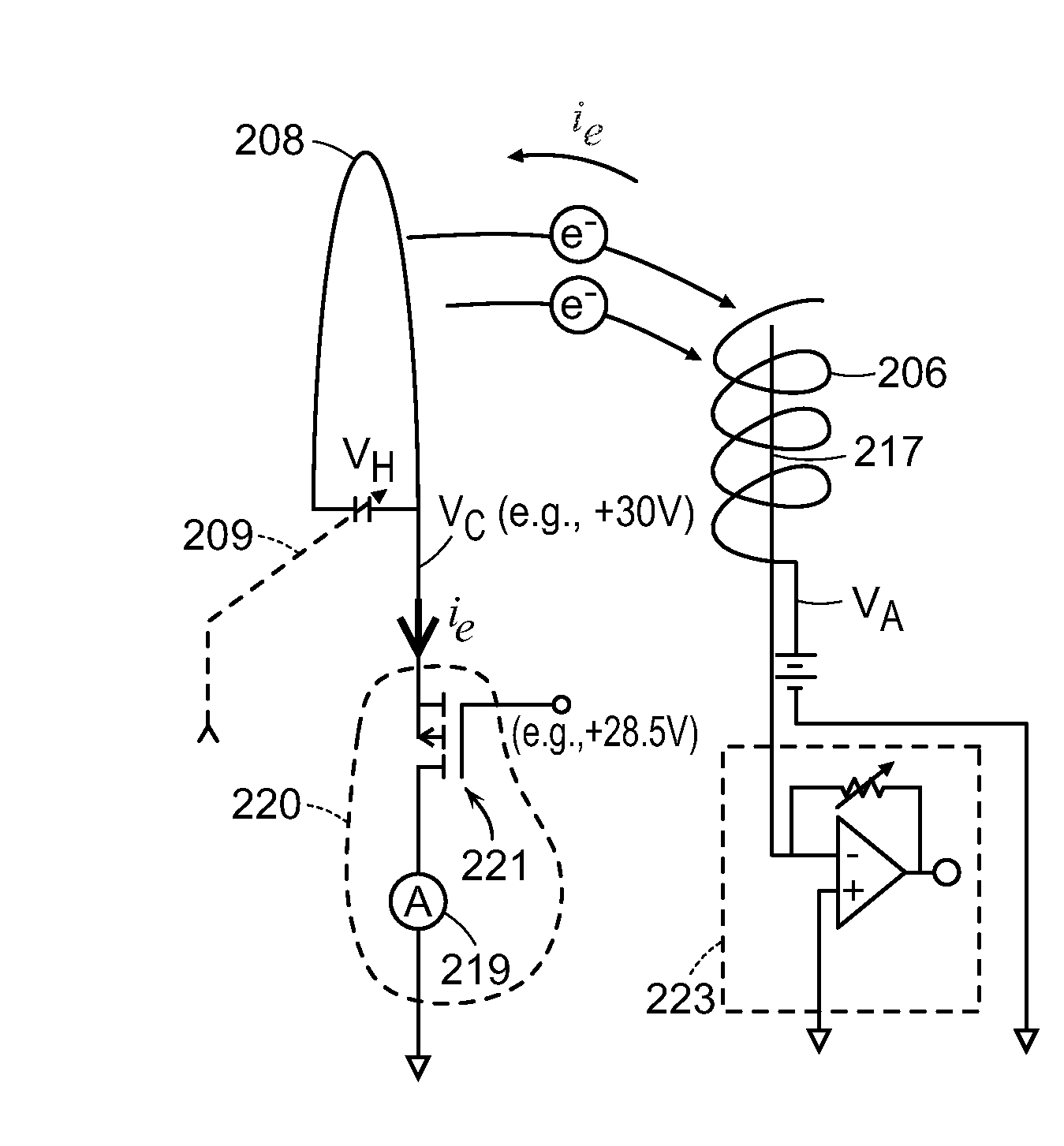
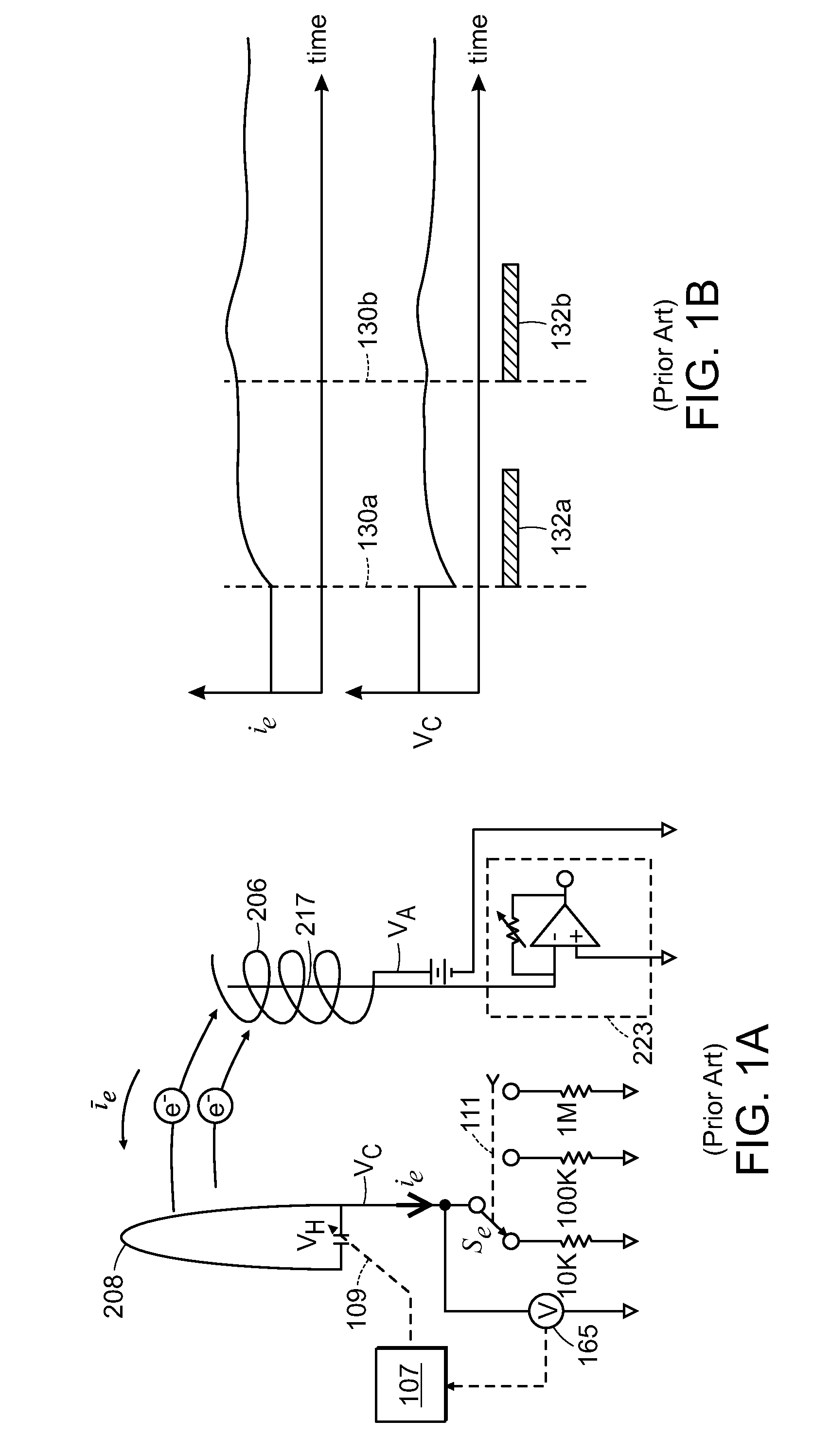
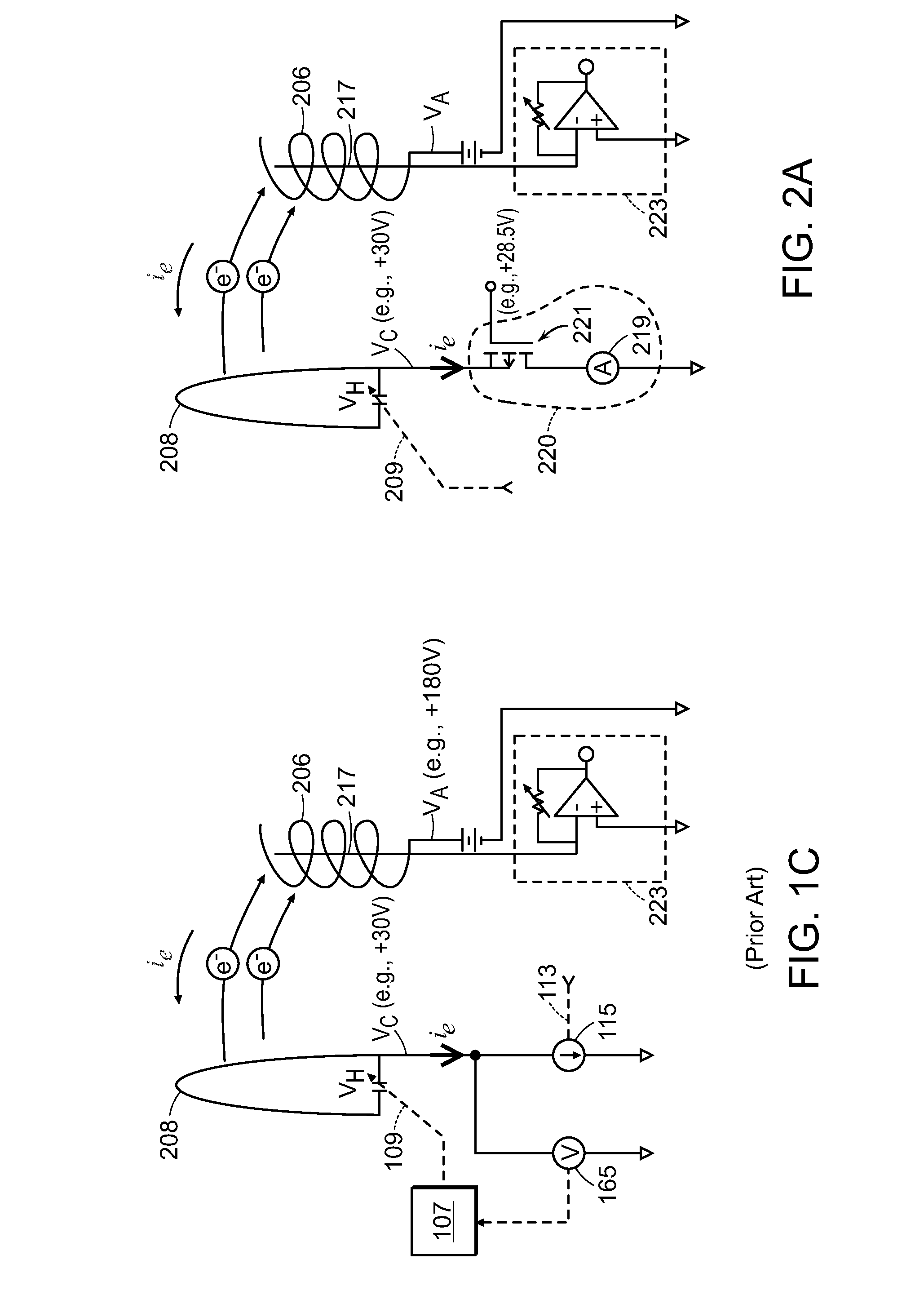
[0028]FIG. 1A illustrates a typical Bayard-Alpert (BA) HCIG. The general principles of operati...


PUM


Abstract

Devices and corresponding methods are provided to operate a hot cathode ionization pressure gauge (HCIG). A transistor circuit can be configured to pass the electron emission current with low input impedance and to control cathode bias voltage. Emission current and cathode bias voltage can be controlled independently of each other, without a servo settling time. HCIGs can be calibrated with respect to leakage current.

Description

BACKGROUND[0001]Ionization vacuum pressure gauges can be used in a wide variety of applications such as semiconductor manufacturing, thin film deposition, high energy physics, ion implantation, and space simulation. Ionization gauges can include both cold cathode ionization gauges (CCIGs) and hot cathode ionization gauges (HCIGs), and some example HCIG designs include Bayard-Alpert (BA), Schulz-Phelps, and triode gauges. The sensor of a typical hot cathode ionization vacuum pressure gauge includes a cathode (the electron source, also called the filament), an anode (also called the grid), and an ion collector electrode. For the BA gauge, the cathode is located radially outside of an ionization space (anode volume) defined by the anode. The ion collector electrode is disposed within the anode volume. Electrons travel from the cathode toward and through the anode, and are eventually collected by the anode. However, in their travel, the electrons impact molecules and atoms of gas, const...

Claims


Application Information

Patent Timeline
IPC IPC(8): G01L21/32
CPCG01L21/32G01L1/144G01L21/30G01L21/34
Inventor HANSEN, DOUGLAS C.
Owner MKS INSTR INC
Why Eureka
Try Eureka