Method for fusing insulated wires, and fused wires produced by such method

a technology of insulated wires and fused wires, which is applied in the field of insulated wires, can solve the problems of not always a desirable method, difficult, if not impossible, to avoid deformation of insulation coatings, and achieves low pull-apart strength, low cost, and high degree of retained integrity

Active Publication Date: 2010-09-30
FORT WAYNE METALS RES PROD CORP
View PDF22 Cites 15 Cited by
  • Summary
  • Abstract
  • Description
  • Claims
  • Application Information

AI Technical Summary

Benefits of technology

[0014]Advantageously, by the present method, insulated wires can be brought together in a close contacting adjacent relationship to ensure that the coatings of the wires are just barely touching one another prior to any heat being applied to the wires. Subsequent heating ensures that the wires are fused only along a minimal line contact between the insulation coatings, thereby minimizing or preventing deformation of the insulation coatings of the wires while producing a bond strength between the individual coatings adequate to ensure that the pair remains firmly joined. The resulting fused wire has a low pull-apart strength and a high degree of retained integrity for the individual insulation coatings. The combined diameter of the fused wire equals, or very closely matches, the combined diameters of the individual wires prior to fusion.

Problems solved by technology

However, co-extrusion has certain disadvantages and is not always a desirable method, particularly when forming dual conductor wires that need to be attached along a minimal, or line, contact such that the round cross sectional shapes of the individual insulation coatings of the individual wires is maintained.
With each of these methods, it is necessary to bring the coated wires as close to one another as possible while the insulation is heated and is not fully cured, and it is very difficult, if not impossible, to avoid deforming the insulation coatings as the wires are pressed together, such that a significant amount of the coating of one wire flows into or around, or blends into, the coating of the other wire, and vice-versa.

Method used


Image

  • Method for fusing insulated wires, and fused wires produced by such method
  • Method for fusing insulated wires, and fused wires produced by such method
  • Method for fusing insulated wires, and fused wires produced by such method

Examples


example 1

Fusion of Wire Pairs Made from 316LVM, 35N LT®, and Pt / 10% Ir Conductors Having ETFE Coatings

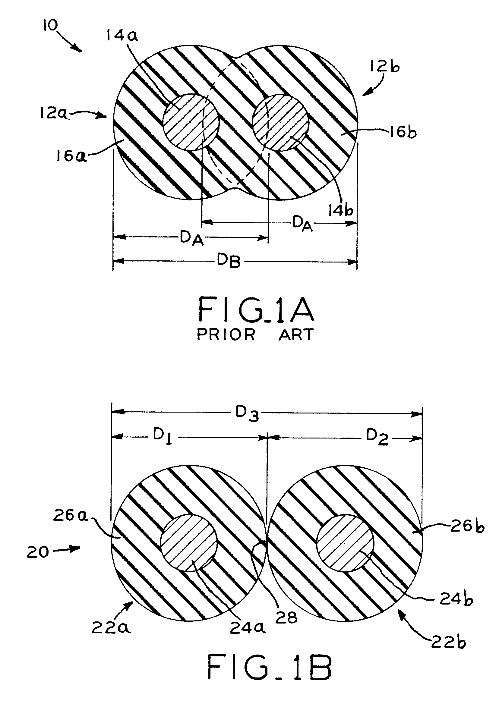
[0091]In this Example, wire pairs were fused using the above-described apparatus. The wires had coatings formed from an ethylene tetrafluoroethylene copolymer (ETFE) and had outer diameters (D1 and D2) of 0.0121 inch (0.0307 cm). The spacing between the apexes 54 of grooves 52a and 52b of pulley 50, and the spacing between the apexes 60 of grooves 58a and 58b of pulley 56, were each 0.09 inch (0.2286 cm).

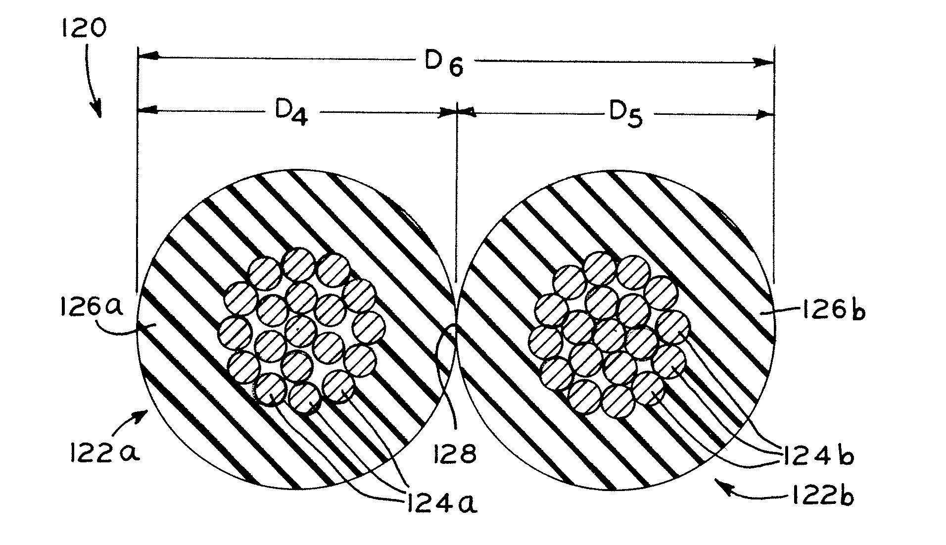
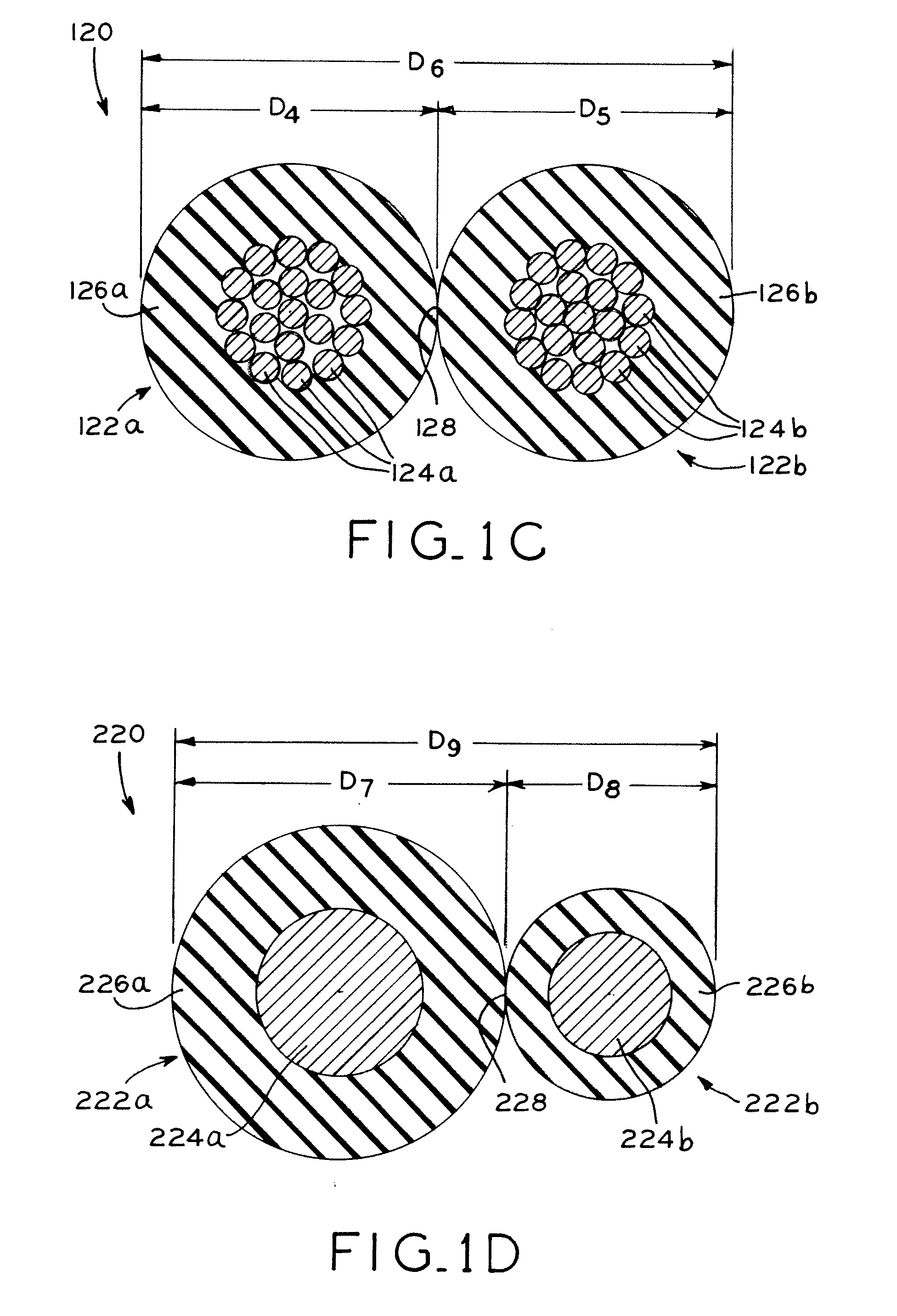
[0092]As set forth in Table 1 below, the wires had conductors made from 316LVM stainless steel, 35N LT® (an MP35N alloy available from Fort Wayne Metals Research Products Corporation of Fort Wayne, Ind.), and an alloy of 90% platinum / 10% iridium (Pt10 / Ir). Seven runs were conducted, each using two wires of the given construction and under the conditions set forth in Table 1 below. In each run, a laser micrometer measurement device was used to measure the combined or major diameter D3 of the ...


PUM

PropertyMeasurementUnit
diameter D1aaaaaaaaaa
diameter D2aaaaaaaaaa
diameter D3aaaaaaaaaa

Abstract

A method for fusing a pair of insulated wires to one another, and a fused wire made by such method, in which the combined or major diameter of the fused wire equals, or very closely matches, the sum of the diameters of the individual wires prior to fusion. In the present method, a pair of wires, each having a coating of insulation that is substantially fully cured, are brought into close abutting contact with one another along a line contact, and thereafter pass through a heating device which heats the coatings above their a thermal transition point of at least one of the pair of wires to fuse the coatings of the wires together along the line contact.

Description

CROSS REFERENCE TO RELATED APPLICATION[0001]This application claims the benefit under Title 35, U.S.C. §119(e) of U.S. Provisional Patent Application Ser. No. 61 / 148,492, entitled METHOD FOR FUSING INSULATED WIRES, AND FUSED WIRES PRODUCED BY SUCH METHOD, filed on Jan. 30, 2009, the entire disclosure of which is hereby expressly incorporated herein by reference.BACKGROUND OF THE INVENTION[0002]1. Technical Field[0003]The present disclosure relates to insulated wires and, in particular, relates to a method of fusing a pair of insulated wires together, and a fused wire made in accordance with such method.[0004]2. Description of the Related Art[0005]Insulated wires are well known for use in many applications, and are formed by coating a metal conductor wire with a coating of insulation material. The metal conductor wire may be an individual wire, or may be a strand made by twisting a plurality of individual metal wires together. Typically, the metal wires are coated by an extrusion pro...

Claims


Application Information

Patent Timeline
Patent Type & Authority Applications(United States)
IPC IPC(8): H01B7/08H01B7/00B32B37/02
CPCH01B7/048H01B13/0023
Inventor TELLEY, SEAN P.STACEY, CHRISTIAN W.
Owner FORT WAYNE METALS RES PROD CORP
Why Eureka
Try Eureka