Sensor assembly and method for producing a sensor assembly

a technology of sensor assembly and assembly method, which is applied in the direction of speed/acceleration/shock measurement, measurement apparatus components, instruments, etc., can solve the problems of not being able to transfer pressure onto the semiconductor sensor element, not being able to integrate the semiconductor sensor element into the housing, and being susceptible to breakage of semiconductor materials, etc., to achieve the effect of simple manner

Active Publication Date: 2020-10-01
ROBERT BOSCH GMBH
View PDF0 Cites 0 Cited by
  • Summary
  • Abstract
  • Description
  • Claims
  • Application Information

AI Technical Summary

Benefits of technology

[0009]Advantageously, the housed semiconductor sensor element may rest with the outer edge region of its bottom side directly on a supporting surface of the holder body surrounding the receiving space or on a supporting surface of another component situated on the holder body which surrounds the receiving space. The supporting surface advantageously allows for a defined orientation of the housed semiconductor sensor element in a direction perpendicular to the mounting surface. This is advantageous especially in the case of Hall ICs or ASICs having a Hall IC, since here the orientation of the Hall IC is an important parameter for the detection of the magnetic field of a pulse-generator wheel.
[0010]The mounting surface may be recessed with respect to the supporting surface viewed in a direction perpendicular to the mounting surface, which creates a receiving space for the adhesive in a simple manner. The adhesive may be introduced into this receiving space for example by a dispenser without dirtying the supporting surface.

Problems solved by technology

In these sensor assemblies, however, the semiconductor sensor element is not integrated into a housing.
Furthermore, here the semiconductor sensor element used for measuring pressure fundamentally cannot be covered by a cured enveloping material since then it would no longer be possible to transfer pressure onto the semiconductor sensor element.
Experience shows that semiconductor materials are susceptible to breakage.
In the application of such an enveloping material, which may also be performed by injection molding for example, forces act on the breakable semiconductor sensor element from all sides, which may result in a displacement of the housed semiconductor sensor element and in the unfavorable case in a breakage of the semiconductor sensor element contained in the housing.

Method used


Image

  • Sensor assembly and method for producing a sensor assembly

Examples


Embodiment Construction

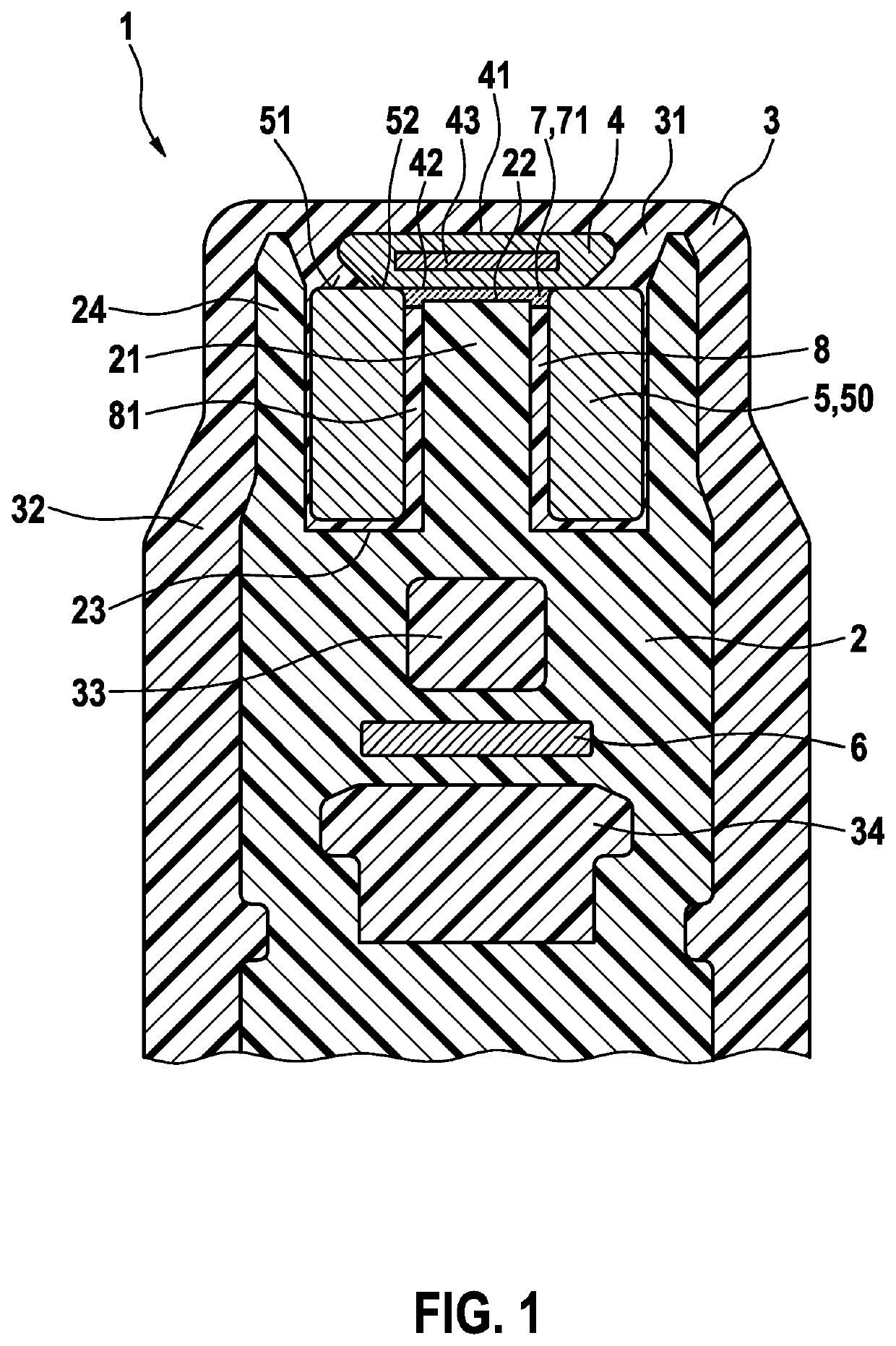
[0019]FIG. 1 shows a detail of a cross section through the head section of a sensor assembly 1.

[0020]Sensor assembly 1 has a holder body 2 made of plastic for example. Holder body 2 may be produced for example as an injection molded part by spray-coating metallic lead frame strips 6. In a head section of holder body 2, an annular groove 23 is provided, which may be situated concentrically around a mounting base 21. At the extreme, a mounting surface 22 is formed on mounting base 21. Mounting surface 22 is preferably formed as a flat surface. Annular groove 23 may be flanked by a, preferably elastic, circumferential wall 24 formed on holder body 2, which may project a bit beyond it in the direction toward mounting surface 22.

[0021]A component 5 is pressed into annular groove 23, which may be for example an annular magnet 50 of sensor assembly 1. For this purpose, clamping arrangement (not shown) may be situated on the inner wall of annular groove 23, which make it possible to clamp a...


PUM

PropertyMeasurementUnit
rotational speedaaaaaaaaaa
moldingaaaaaaaaaa
magnetic fieldaaaaaaaaaa

Abstract

A sensor assembly comprising a holder body and a housed semiconductor sensor element situated on the holder body for rotational speed measurement and/or position measurement, a cured enveloping material that covers the housed semiconductor sensor element completely being situated on the holder body. It is provided that the housed semiconductor sensor element is glued onto a mounting surface of the holder body using an adhesive that differs from the enveloping material, and that the adhesive is situated in a receiving space between the mounting surface and a bottom side of the housed semiconductor sensor element that is facing the mounting surface.

Description

BACKGROUND INFORMATION[0001]Sensor assemblies, which have a semiconductor sensor element for rotational speed measurement and / or position measurement, are used in manifold ways in the related art. Hall IC components or ASICs (application-specific integrated circuit) having a Hall IC are used for example as housed semiconductor elements, which are embedded in a housing. Such sensors are often used in combination with magnetic or non-magnetic pulse-generator wheels for rotational speed measurement. If a pulse-generator wheel having teeth or tooth gaps rotates in front of the front side of the sensor assembly, this causes a change in the magnetic field at the location of the semiconductor sensor element, which produces an electrical signal as a function of the passing teeth and tooth gaps, from which the rotational speed of the pulse-generator wheel may be determined. Additionally or alternatively, such sensor assemblies may also be used for example in combination with encoded pulse-ge...

Claims


Application Information

Patent Timeline
Patent Type & Authority Applications(United States)
IPC IPC(8): G01P1/02G01D5/14G01P3/487G01D11/30
CPCG01D11/30G01P1/026G01D5/145G01P3/487G01D11/245
Inventor ELZNER, MATHIASULLMANN, THOMAS
Owner ROBERT BOSCH GMBH
Why Eureka
Try Eureka