Device and method for performing a localized induction hardening treatment on mechanical components, specifically thrust blocks for large-sized rolling bearings

a technology of mechanical components and hardening treatment, which is applied in the direction of induction heating, induction heating apparatus, furnace types, etc., can solve the problems of poor or inexistent flexibility of employed machines, all these problems have only been minimized but not yet solved, etc., and achieve high heating uniformity of treated parts , the effect of small dimensions

Inactive Publication Date: 2010-09-30
SAET
View PDF3 Cites 20 Cited by
  • Summary
  • Abstract
  • Description
  • Claims
  • Application Information

AI Technical Summary

Benefits of technology

[0004]It is thus the object of the present invention to provide an induction hardening device and method, which overcome the above-described drawbacks, specifically being able of ensuring high production rates and high heating uniformity of the treated parts, regardless of the shape and size of the same, displaying at the same time small dimensions and low construction and operation costs, with a considerable reduction, or even a complete elimination, of the soft zones.
[0007]Said predetermined distance of the inductors from the track is obtained by using a feeler which accurately detects the geometry of the track and which is introduced between the two inductors and then moved away during the heating steps which are performed sequentially in synchronism with the rotation of the thrust block, by means of a stepper motor, and by varying, in a final step, the electric power fed to at least one of the inductors.
[0008]In this manner, it is possible to obtain and maintain a desired hardening profile, with high quality standards, also in presence of tracks having a complex transversal profile, with the presence of concavities for the collection in use of grease for lubricating the rolling elements, without needing to make the inductors follow the profile of the track even at such concavities for grease, with great construction and standardization advantages of the inductors. Surprisingly, a drastic reduction of the extension of the soft zone is also obtained, which zone is anyway harder than those obtainable according to the state of the art.
[0009]Furthermore, the hardening device according to the invention displays a high construction and design simplicity, and a small size as compared to the known induction heating systems for the same application and, above all, a very high flexibility which allows with a single device, and by replacing the inductors only, to harden any type of thrust block, for either radial or axial bearings, with either ball or cylindrical or barrel-shaped rolling elements, having either internal or external tracks.

Problems solved by technology

The induction hardening heat treatment of the thrust block tracks of large-sized bearings displays many problems, the most important of which are the relatively low speed of the hardening process, which does not exceed 300-350 mm / minute, inaccuracies and difficulties to obtain a desired hardening profile, which ideally requires different hardening intensities at different zones of the tracks, the need to have inductors which perfectly “copy” the transversal profile of the track and which therefore may not be used for even only slightly different thrust blocks, and the formation of a partial tempering zone, known as “soft zone”.
Until now, all these problems have only been minimized but not yet solved, though to the detriment of a poor or inexistent flexibility of the employed machines.

Method used


Image

  • Device and method for performing a localized induction hardening treatment on mechanical components, specifically thrust blocks for large-sized rolling bearings
  • Device and method for performing a localized induction hardening treatment on mechanical components, specifically thrust blocks for large-sized rolling bearings
  • Device and method for performing a localized induction hardening treatment on mechanical components, specifically thrust blocks for large-sized rolling bearings

Examples


Embodiment Construction

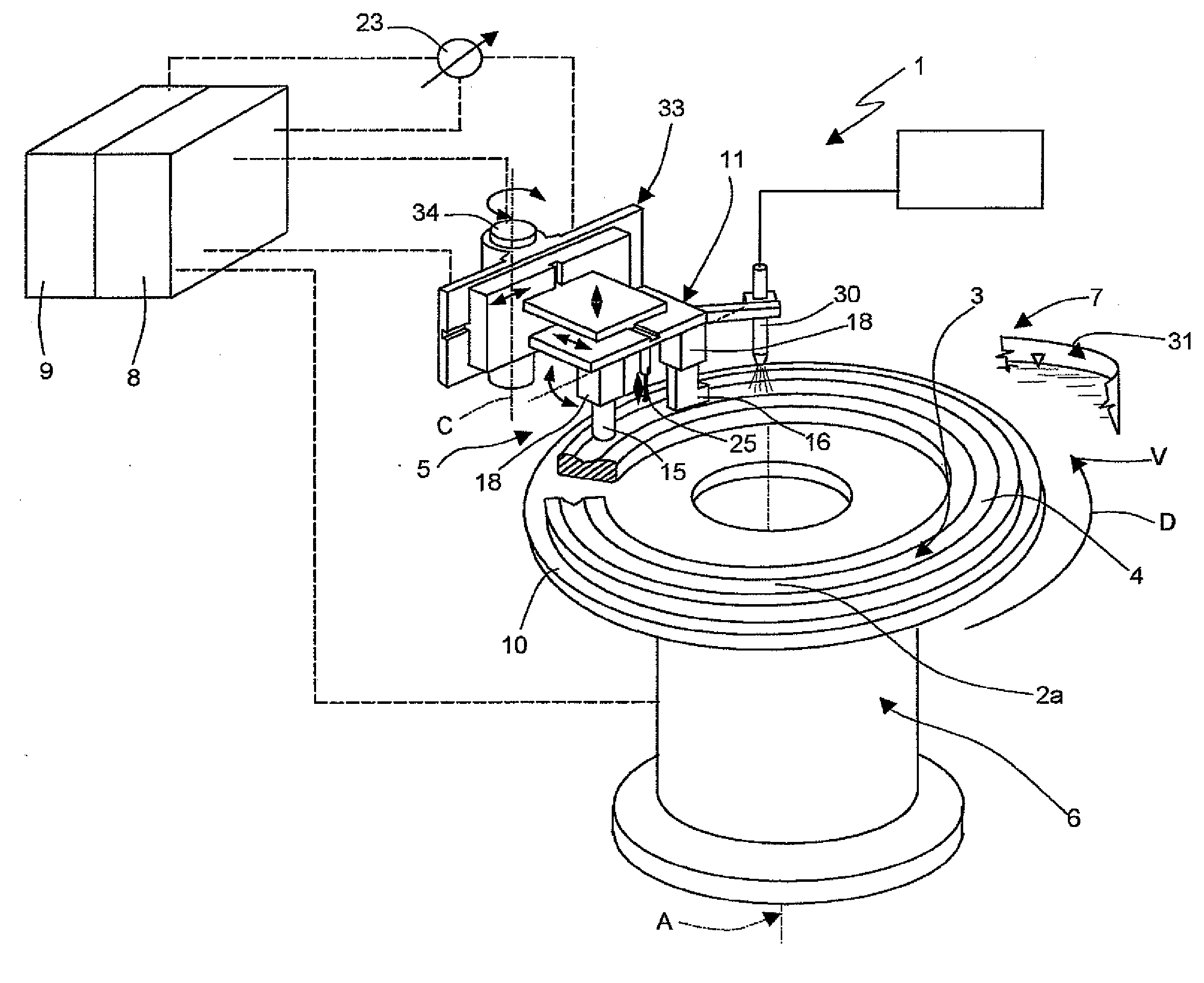
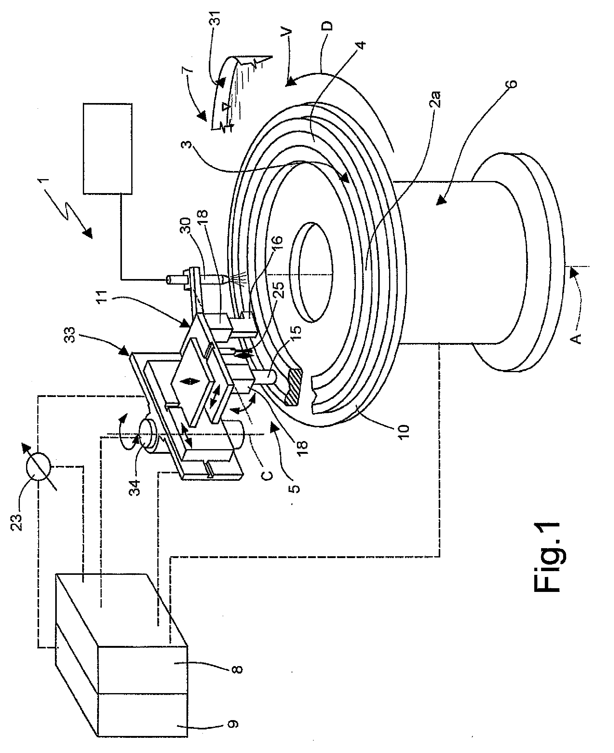
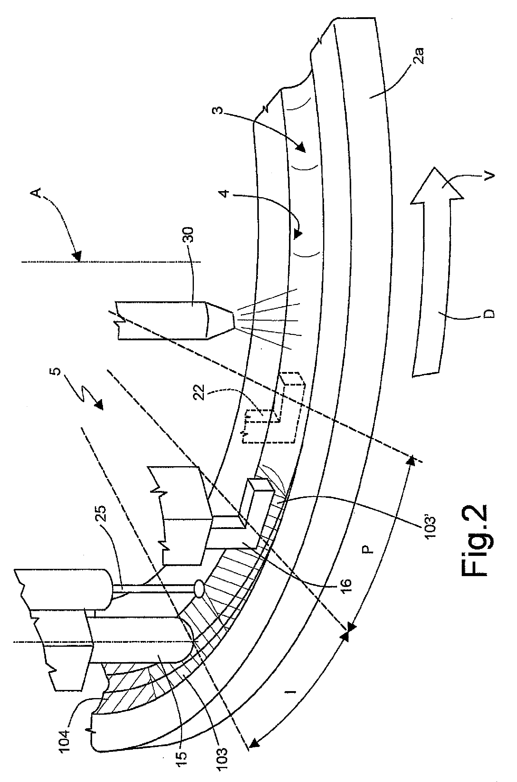
[0017]With reference to figures from 1 to 3, numeral 1 indicates as a whole a device for performing a localized induction hardening on a mechanical component 2; in particular, the present invention is specifically designed not for hardening generic mechanical components, but exclusively annular thrust blocks 2 of large-sized, either radial or axial, rolling bearings (which can even reach several meters in size), e.g. intended to equip wind generators, drills and special machines in general; even more specifically, the device 1 is designed, as will be seen, to harden a specific portion of each thrust block 2 consisting of a surface 3 of an annular rolling track 4 for the rolling elements of the bearings, according to a required hardening profile.

[0018]As many known hardening devices, the device 1 (FIG. 1) includes induction heating means 5, means 6 for moving the induction heating means 5 relative to the mechanical component 2 (hereinafter, explicit reference will be made to thrust b...


PUM

PropertyMeasurementUnit
speedsaaaaaaaaaa
speedsaaaaaaaaaa
distanceaaaaaaaaaa

Abstract

A device and method for induction hardening rolling tracks of thrust blocks of bearings, according to a required hardening profile. At least two inductors arranged in tandem are used within a track to be hardened, at a predetermined distance from a surface of the track and the thrust block is rotated with respect to the inductors, so as to make them cover the entire track, with a complete 360° turn; the inductors, at least one first pre-heating inductor and one at least heating inductor, are shaped so as to generate a first and a second magnetic fields, respectively, both having flux lines which are perpendicular to each other, and one of the two inductors is mounted on an orientable head so as to be able to arrange the two inductors oriented according to the curvature of the track. The mentioned predetermined distance of the inductors from the track is obtained by using a feeler to accurately detect the geometry of the track and which is introduced between the two inductors and then moved away during the heating steps which are performed sequentially in synchronism with the rotation of the thrust block, and by varying, in a final step, the electric power fed to at least one inductor.

Description

[0001]The present invention relates to a device and to a method for performing a localized induction hardening treatment on mechanical components, specifically for hardening thrust block tracks of large-sized rolling bearings.BACKGROUND OF THE INVENTION[0002]The induction hardening heat treatment of the thrust block tracks of large-sized bearings displays many problems, the most important of which are the relatively low speed of the hardening process, which does not exceed 300-350 mm / minute, inaccuracies and difficulties to obtain a desired hardening profile, which ideally requires different hardening intensities at different zones of the tracks, the need to have inductors which perfectly “copy” the transversal profile of the track and which therefore may not be used for even only slightly different thrust blocks, and the formation of a partial tempering zone, known as “soft zone”.[0003]Until now, all these problems have only been minimized but not yet solved, though to the detrimen...

Claims


Application Information

Patent Timeline
Patent Type & Authority Applications(United States)
IPC IPC(8): H05B6/10
CPCC21D1/10H05B6/38H05B6/101C21D9/40Y02P10/25
Inventor CESANO, MARIOLINOCENA, CARLO
Owner SAET
Why Eureka
Try Eureka